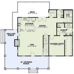
Electrical Wiring House Plans Dwg: Essential Aspects
Electrical wiring house plans dwg, also known as electrical blueprints, are technical drawings that provide detailed instructions for the electrical wiring of a building. These plans are essential for ensuring the safety and functionality of electrical systems, and they are required for obtaining building permits and passing inspections.
Electrical wiring house plans dwg typically include the following information:
- Floor plans showing the location of electrical outlets, switches, and fixtures
- Circuit diagrams showing the electrical circuits and their connection to the electrical panel
- Panel schedules listing the circuits and their corresponding breakers
- Load calculations determining the electrical load on each circuit and the size of the wiring required
- Legend explaining the symbols and abbreviations used on the plans
When creating electrical wiring house plans dwg, it is important to follow the National Electrical Code (NEC) and local building codes. These codes provide minimum safety standards for electrical installations and ensure that the plans are compliant with the requirements of the local authority.
Electrical wiring house plans dwg are essential for the successful completion of any electrical project. By providing detailed instructions for the installation of electrical systems, these plans help to ensure the safety and functionality of the building's electrical systems.
Benefits of Using Electrical Wiring House Plans Dwg
There are many benefits to using electrical wiring house plans dwg when designing and installing electrical systems. These benefits include:
- Improved safety: Electrical wiring house plans dwg help to ensure that electrical systems are installed safely and in accordance with code requirements.
- Increased efficiency: By providing a clear and concise plan for the installation of electrical systems, electrical wiring house plans dwg can help to improve the efficiency of the installation process.
- Reduced costs: By avoiding costly mistakes and rework, electrical wiring house plans dwg can help to reduce the overall cost of electrical installations.
- Improved communication: Electrical wiring house plans dwg provide a common language for all parties involved in the electrical installation process, helping to improve communication and coordination.
Overall, electrical wiring house plans dwg are an essential tool for anyone involved in the design and installation of electrical systems. By providing detailed and accurate instructions, these plans help to ensure the safety, efficiency, and cost-effectiveness of electrical installations.
How to Create Electrical Wiring House Plans Dwg
Creating electrical wiring house plans dwg can be a complex and time-consuming task. However, there are a number of software programs available that can make the process easier. These programs allow users to create detailed electrical plans quickly and easily, and they can also help to ensure that the plans are compliant with code requirements.
When creating electrical wiring house plans dwg, it is important to follow these steps:
- Gather the necessary information. This includes the floor plans of the building, the location of electrical outlets, switches, and fixtures, and the size of the electrical load on each circuit.
- Choose the appropriate software program. There are a number of different software programs available that can be used to create electrical wiring house plans dwg. Choose a program that is easy to use and that meets your specific needs.
- Create the floor plans. The floor plans should show the location of all electrical outlets, switches, and fixtures. They should also include dimensions and other relevant information.
- Create the circuit diagrams. The circuit diagrams should show the electrical circuits and their connection to the electrical panel. They should also include the size of the wire and the type of circuit breaker used on each circuit.
- Create the panel schedules. The panel schedules should list the circuits and their corresponding breakers. They should also include the size of the breaker and the type of circuit.
- Create the load calculations. The load calculations should determine the electrical load on each circuit. This information is used to size the wiring and the circuit breakers.
- Create the legend. The legend should explain the symbols and abbreviations used on the plans.
Once the electrical wiring house plans dwg are complete, they should be reviewed by a qualified electrician to ensure that they are accurate and compliant with code requirements.

House Electrical Plan In Autocad File Layout Residential Cad

Home Electrical Drawings Cad Pro

Electrical Layout Plan Of Modern House Autocad File Kitchen Plans

Home Electrical Plan Design Autocad File House Wiring

House Electrical Wiring Plan Autocad Drawing Residential

Big House Electrical Layout Plan Autocad Drawing Houses

Single Family Dwelling House Electric Installation Dwg File Cadbull

Electrical Drawings Cad Drawing

Home Installation In Autocad Cad Free 298 94 Kb Bibliocad

Electric Layout Plan Of House With Detail Dimension In Autocad Electrical Cad Drawing Residential


