Understanding House Elevation Plan Images
House elevation plan images are crucial architectural drawings that visually represent the exterior appearance of a house from a particular viewpoint. These plans are distinct from floor plans, which depict the interior layout. Elevation plans focus on the vertical aspects of the building, illustrating the height, width, and architectural details of the facades. They are essential for visualizing the finished product, obtaining necessary approvals, and ensuring accurate construction.
Understanding house elevation plan images is vital for homeowners, builders, and architects alike. They offer a clear understanding of the aesthetic qualities of the building, revealing design choices related to windows, doors, roofing, siding, and other exterior features. These images also provide critical information regarding the dimensions and placement of these elements, facilitating accurate construction and preventing potential issues. Furthermore, elevation plans serve as a communication tool between the designer, contractor, and client, ensuring everyone is on the same page regarding the project's visual outcome.
Elevation plans are typically drawn after the floor plans have been finalized. The floor plans define the internal arrangement of the house, while the elevation plans address the exterior appearance. Architects create elevations from multiple viewpoints – typically front, rear, and sides – to provide a comprehensive view of the building's external characteristics. These views demonstrate how the home will appear in its surrounding environment and how the various facade elements integrate to create a cohesive architectural statement.
Key Elements Displayed in House Elevation Plan Images
House elevation plan images contain numerous details that convey essential information about the building's exterior. These elements contribute to an overall understanding of the design and construction process. The following are some of the key elements typically included in elevation plans:
1. Exterior Walls and Materials: Elevation plans clearly illustrate the types of materials used for the exterior walls, such as brick, siding, stucco, or stone. They will also show the precise location and dimensions of each material, ensuring accurate installation. Different materials can have unique visual effects, and the elevation plan allows for the assessment of this visual impact before construction begins. Furthermore, details like the texture and color of the materials can sometimes be indicated, though these finer details may be more fully expressed in separate material schedules or renderings.
2. Doors and Windows: The size, shape, and placement of all doors and windows are accurately depicted in elevation plans. The type of window (e.g., double-hung, casement, sliding) is indicated, as is the style of door (e.g., panel, glass, sliding). The plans also show the trim around the doors and windows, contributing to the overall aesthetic of the facade. These details are crucial for ensuring proper window and door installation, as well as for evaluating the overall architectural integrity of the design.
3. Roof Details: Elevation plans provide a clear view of the roofline, including the pitch, overhang, and materials used. They indicate the type of roofing material (e.g., shingles, tile, metal) and the style of the roof (e.g., gable, hip, shed). Elements such as chimneys, vents, and skylights are also shown, contributing to a comprehensive understanding of the roof's design and functionality. The accuracy of these details is essential for proper roof construction and weatherproofing.
4. Grade Line and Site Features: The elevation plan shows the relationship between the building and the surrounding landscape. The grade line indicates the level of the ground in relation to the building's foundation. Any landscaping features, such as patios, decks, walkways, and retaining walls, are also included. This information is crucial for ensuring proper drainage and for visualizing how the building will integrate with its environment. It also aids in planning the site grading and landscaping, which are essential for both aesthetic appeal and functional purposes like water management.
5. Architectural Details: Elevation plans also depict specific architectural details that enhance the building's aesthetic appeal. These details may include columns, pilasters, cornices, brackets, railings, and other decorative elements. The plans show the size, shape, and placement of these elements, ensuring accurate construction and contributing to the overall visual character of the building. These details often reflect the architectural style of the house, whether it is traditional, modern, or contemporary.
Types of House Elevation Plan Images
Elevation plans are typically categorized based on the direction from which the house is viewed. Each type of elevation provides a unique perspective and highlights different aspects of the building's exterior. The four main types of elevation plans are:
1. Front Elevation: This is the most common type of elevation plan and shows the front facade of the house, typically the side that faces the street. It highlights the main entrance, any prominent architectural features, and the overall aesthetic appeal of the building's front face. The front elevation is often the primary image used for marketing and presentation purposes, as it provides the first impression of the house.
2. Rear Elevation: This elevation shows the back of the house. It often depicts elements such as patios, decks, and backyard access points. The rear elevation is important for understanding how the house interacts with the outdoor living space and for planning landscaping and other exterior features. It may also include details related to outdoor entertaining areas or utilitarian features like service entrances.
3. Side Elevations: These elevations show the sides of the house, typically labeled as left and right elevations. They provide a view of the building's profile and reveal details that may not be visible from the front or rear. Side elevations are essential for understanding the overall proportions of the house and for identifying any potential design challenges related to building setbacks or property lines. They also show the placement of windows and doors on the sides of the house, which is critical for ventilation and natural lighting.
4. Interior Elevations: While technically focused on interior elements, these are drawn in the same technical style as exterior elevations. They depict the vertical arrangement of interior walls, cabinets, and appliances within a room, showing their placement and height. They are typically used for kitchen and bathroom designs but may be used for any interior space. Interior elevations are key for visualizing the layout and functionality of interior spaces, ensuring that all elements are properly sized and positioned.
Reading and Interpreting House Elevation Plan Images
Effectively reading and interpreting house elevation plan images requires understanding the conventions and symbols used in architectural drawings. Here are some key points to consider:
1. Understanding Scale: Elevation plans are drawn to scale, meaning that the dimensions on the drawing are proportional to the actual dimensions of the building. The scale is typically indicated on the drawing (e.g., 1/4" = 1'0"), allowing you to calculate the actual size of elements by measuring them on the plan. Accurate interpretation of the scale is crucial for ensuring accurate construction and preventing errors.
2. Identifying Symbols and Abbreviations: Architectural drawings use various symbols and abbreviations to represent different materials, components, and features. A legend or key is typically included on the drawing to explain these symbols and abbreviations. Common symbols may represent different types of building materials, electrical fixtures, or plumbing components. Understanding these symbols is essential for accurately interpreting the information conveyed in the elevation plan.
3. Recognizing Line Weights: Line weights are used to differentiate between different elements in the elevation plan. Thicker lines typically indicate prominent features, such as exterior walls, while thinner lines are used for less critical details, such as window trim or siding. Varying line weights help to create visual hierarchy and make the drawing easier to read.
4. Checking Dimensions and Annotations: Elevation plans include dimensions that specify the height, width, and depth of various elements. Annotations provide additional information about materials, finishes, and construction details. These dimensions and annotations are crucial for ensuring accurate construction and for understanding the design intent. Always double-check the dimensions and annotations to verify that they are consistent with the overall design and that they meet any applicable building codes or regulations.
5. Cross-Referencing with Other Plans: Elevation plans should be cross-referenced with other architectural drawings, such as floor plans, site plans, and section drawings, to gain a complete understanding of the building's design. Floor plans show the interior layout, site plans show the building's location on the property, and section drawings show a vertical cut through the building. By cross-referencing these drawings, you can gain a comprehensive understanding of how the building's exterior relates to its interior and its surrounding environment.
By understanding these key elements, types, and interpretation techniques, individuals can more effectively utilize house elevation plan images for visualization, planning, and construction purposes. These detailed drawings are indispensable tools for bringing architectural visions to life.

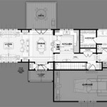
Floor Plan Elevation Sample

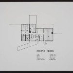
Scheme Of The Tested Single Family House A Front Elevation B Scientific Diagram

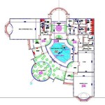
Architecture House Plan And Elevation Complete Drawing

Front Elevation Drawing House Designs Plan

Elevations Styles Home Elevation Design House

I Ll Draw 2d Floor Plan Section Elevation In Autocad And Revit For 30 Freelancer Ekundayo Rilwan Realoneconsult Kwork

What Are Elevations Building Design House

House Plan And Front Elevation Drawing File 630 Sqf Cadbull

House Elevation Drawing With Detailed Dimensions

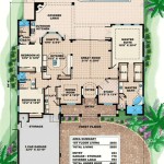
20 Ground Floor Elevation With Plan