What Is A Plan Drawing?
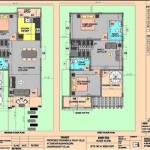
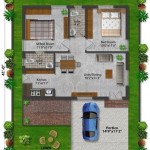
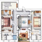
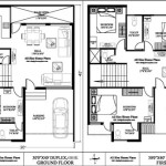
A plan drawing, often simply called a "plan," provides a graphical representation of a design for construction or manufacturing. It's essentially a bird's-eye view, depicting the layout and dimensions of a space or object as if viewed from directly above. Plans are fundamental tools in various fields, including architecture, engineering, landscaping, and product design. They serve as a visual language for communicating design intent and ensuring all stakeholders understand the project scope.
Key Points About Plan Drawings:
- Bird's-eye view perspective.
- Focus on layout and dimensions.
- Essential for construction and manufacturing.
Plan drawings can represent a wide range of projects, from entire building layouts to detailed component designs. In architecture, floor plans show the arrangement of rooms, walls, doors, and windows within a building. Site plans illustrate the location of buildings on a property, including landscaping, parking areas, and utilities. In engineering, plans might depict the layout of piping systems, electrical circuits, or mechanical equipment. In manufacturing, plans detail parts, assemblies, and the overall product structure.
Key Points About Plan Drawing Applications:
- Architectural floor plans for room layouts.
- Site plans for building placement and landscaping.
- Engineering plans for systems and equipment.
- Manufacturing plans for product components and assembly.
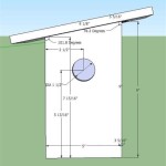
Plan drawings utilize standardized symbols, line weights, and dimensioning techniques to convey information clearly and concisely. These standards ensure that different professionals involved in a project can interpret the drawing accurately. Symbols represent common elements like doors, windows, plumbing fixtures, and electrical outlets. Line weights differentiate between walls, outlines, and hidden features. Dimensions indicate the size and location of elements, ensuring the final product meets the design specifications.
Key Points About Plan Drawing Conventions:
- Standardized symbols for common elements.
- Varied line weights for different features.
- Precise dimensions for accurate construction.
The creation of plan drawings has evolved significantly with the advent of computer-aided design (CAD) software. CAD programs allow for precise drafting, easy modification, and the generation of 3D models based on the 2D plan. These digital tools enhance efficiency, reduce errors, and enable seamless collaboration among different design teams. Different CAD software caters to specific industries and project types, offering specialized tools and features.
Key Points About CAD and Plan Drawings:
- CAD software enables precise drafting.
- Facilitates easy modifications and updates.
- Allows for 3D model generation.
- Enhances collaboration among design teams.
Plan drawings are integral to the project lifecycle, serving various purposes from initial design conceptualization to construction documentation and facility management. During the design phase, plans help visualize the layout and explore different design options. They provide a basis for cost estimation and material take-offs. During construction, plans guide contractors and ensure accurate execution of the design. As-built drawings, created after construction is complete, document the final built condition and serve as a valuable reference for future renovations or maintenance.
Key Points About Plan Drawings in Project Lifecycle:
- Used in design conceptualization and visualization.
- Basis for cost estimation and material procurement.
- Guides construction and ensures design accuracy.
- As-built drawings document the final construction.
Different types of plan drawings exist, each serving a specific purpose. Reflected ceiling plans show the layout of lighting fixtures, ceiling features, and HVAC components. Roof plans illustrate the roof structure, including slopes, drainage systems, and roof openings. Section drawings, while not strictly plans, are closely related and provide a cut-away view of a building or object, revealing internal construction details. Elevation drawings depict the exterior facade of a building, showing window and door placements, wall finishes, and other architectural features.
Key Points About Different Plan Drawing Types:
- Reflected ceiling plans for lighting and HVAC layout.
- Roof plans for roof structure and drainage.
- Section drawings for internal construction details.
- Elevation drawings for exterior facade representation.
Understanding plan drawings is crucial for anyone involved in design, construction, or manufacturing processes. The ability to interpret and utilize plan information effectively ensures clear communication, accurate execution, and successful project outcomes. Properly documented plans contribute to efficient workflows, minimize errors, and facilitate better collaboration amongst project stakeholders. They are the foundation upon which successful projects are built.
Key Points about the Importance of Understanding Plan Drawings:
- Essential for clear communication and accurate execution.
- Contributes to efficient workflows and minimizes errors.
- Facilitates collaboration among project stakeholders.

Floor Plan Wikipedia

Floor Plans Learn How To Design And Plan

Example Of House Plan Drawing Scientific Diagram

House Plan Drawing Everything You Need To Know

The Importance Of 2d Floor Plan Drawings For Architectural Design

Draw Floor Plans In Half The Time Cedreo

Drawing Floor Plan 101 Basic Principles Esoft

Building Planning Drawing Service In Chennai Id 2852687974355

Floor Plan Designing Buildings

Floor Plan Design Tutorial