Creating Plan, Section, and Elevation Drawings of Houses in AutoCAD Civil 3D
AutoCAD Civil 3D, while primarily known for civil engineering applications, can also be effectively utilized for architectural design, including the creation of plan, section, and elevation drawings for houses. While AutoCAD Architecture might be considered the more conventional choice for architectural work, Civil 3D offers certain advantages, particularly when the house design needs to integrate with the surrounding terrain, utilities, and existing site conditions. This article outlines the key considerations and steps involved in developing these crucial architectural drawings within the Civil 3D environment.
The process begins with establishing a robust project setup. This entails configuring the drawing settings, including units, scale, and coordinate system. Choosing an appropriate coordinate system is paramount, especially if the design needs to align with georeferenced site survey data. Careful planning during this initial phase provides a solid foundation for subsequent design endeavors and ensures accuracy throughout the project lifecycle.
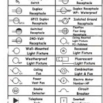
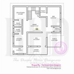
Once the project setup is complete, the creation of the house plan can commence. This involves drawing the walls, doors, windows, and other architectural elements. Civil 3D's object snaps and coordinate entry tools facilitate precise placement. Efficient layering practices are crucial for organizing the different components of the building, such as walls, electrical systems, and plumbing. This organization allows for selective display and manipulation of specific elements during the design process and simplifies the creation of different drawing sets such as architectural, electrical, and plumbing plans.
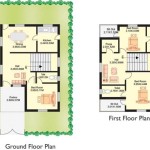
Following the creation of the plan, the process moves onto generating the section and elevation drawings. These drawings provide crucial information about the vertical dimensions and appearance of the house from different perspectives. Using Civil 3D's section and elevation tools, designers can extract these views directly from the 3D model of the house. This direct extraction ensures consistency between the plan, section, and elevation drawings, reducing the risk of errors and discrepancies.
The creation of section and elevation drawings involves defining the cutting planes or viewpoints from which the sections and elevations are to be generated. Once these cutting planes are defined, Civil 3D automatically generates the corresponding views. The generated views can then be further refined by adding annotations, dimensions, and other details to communicate the design intent clearly and effectively. Understanding how to manipulate viewport scales and annotation scales within Civil 3D is crucial for producing drawings that are legible and conform to industry standards.
When integrating the house design with site terrain, Civil 3D's surface modeling capabilities come into play. A surface model representing the existing site topography can be imported from survey data or created using Civil 3D's surface tools. The house model can then be positioned on the surface, and Civil 3D can be used to analyze the impact of the house on the existing terrain. This analysis can inform decisions regarding grading, drainage, and retaining walls, ensuring that the house integrates seamlessly with the surrounding environment.
Key Point 1: Leveraging Civil 3D's 3D Modeling Capabilities
Civil 3D's powerful 3D modeling capabilities are not limited to civil engineering projects. They can be effectively employed to create a detailed 3D model of the house. This model serves as the central source of information for generating the plan, section, and elevation drawings. The 3D model allows for visualization of the house from any angle, facilitating design review and communication with stakeholders. Furthermore, the 3D model can be used for clash detection, identifying potential conflicts between different building systems, such as HVAC and plumbing, early in the design process. This early detection can save time and money by preventing costly rework during construction.
The process of creating the 3D model involves using Civil 3D's object creation tools to draw walls, slabs, roofs, and other architectural elements. These elements can be assigned properties, such as material, thickness, and color, to create a realistic representation of the house. The use of blocks and dynamic blocks can streamline the process of modeling repetitive elements, such as doors and windows. Dynamic blocks allow for easy modification of the size, position, and other parameters of these elements, making it easy to adjust the design as needed. It is important to accurately represent structural components within the 3D model as well.
Civil 3D also allows for the import of 3D models from other software programs, such as Revit or SketchUp. This can be useful if the house has already been modeled in another program. However, it is important to ensure that the imported model is compatible with Civil 3D and that it is accurately positioned in the correct coordinate system. After importing the model, it may be necessary to make modifications to ensure that it meets the specific requirements of the project. The ability to integrate models from different sources allows for a collaborative design process, where architects and engineers can work together seamlessly.
Key Point 2: Integrating with Survey Data and Site Context
A significant advantage of using Civil 3D for house design is its seamless integration with survey data and site context. This integration is crucial for ensuring that the house design is responsive to the existing site conditions and that it minimizes environmental impact. Survey data, including topographic information, boundary lines, and utility locations, can be imported into Civil 3D and used to create a realistic representation of the site. The house model can then be positioned on the site, and Civil 3D can be used to analyze the impact of the house on the surrounding environment.
One important aspect of this integration is the creation of a digital terrain model (DTM) representing the existing site topography. The DTM can be created from survey data or from LiDAR data. Once the DTM is created, Civil 3D can be used to perform various analyses, such as cut and fill calculations, drainage analysis, and slope analysis. These analyses can inform decisions regarding site grading, drainage design, and erosion control. They can also help to identify potential environmental impacts, such as increased runoff or soil erosion. The ability to perform these analyses within Civil 3D allows for a more sustainable and environmentally responsible design process.
Furthermore, Civil 3D can be used to model existing utilities, such as water lines, sewer lines, and gas lines. This information is crucial for avoiding conflicts during construction and for ensuring that the house design does not negatively impact existing utility infrastructure. The location of underground utilities can be obtained from utility companies or from site surveys. Civil 3D's pipe network tools can be used to create a 3D model of the existing utilities, which can then be overlaid on the house model. This allows for easy identification of potential conflicts and for the development of mitigation strategies.
Key Point 3: Generating and Customizing Section and Elevation Views
Generating section and elevation views in Civil 3D is streamlined through its dedicated tools and workflows. These tools allow users to define section lines and generate dynamic section views that automatically update when the 3D model is modified. This dynamic linking ensures that the drawings always reflect the most up-to-date design. The generated section and elevation views can then be customized with annotations, dimensions, and hatching to convey the design intent clearly and effectively. Customization options are crucial for complying with different architectural styles and standards.
The process of creating section views involves defining the section line, which represents the cutting plane through the house model. The section line can be drawn interactively or defined by specifying coordinates. Once the section line is defined, Civil 3D automatically generates the section view, which shows the interior of the house as if it were cut along the section line. The section view can be customized by adding annotations, dimensions, and hatching to highlight specific features. For example, wall thicknesses, floor heights, and roof slopes can be dimensioned, and different materials can be represented using different hatching patterns.
Similarly, elevation views are generated by defining a viewpoint from which the house is to be viewed. The viewpoint can be defined by specifying its location and orientation. Once the viewpoint is defined, Civil 3D automatically generates the elevation view, which shows the exterior of the house from that perspective. The elevation view can be customized by adding annotations, dimensions, and other details to communicate the design intent clearly. For example, window sizes, door locations, and roof overhangs can be dimensioned, and different exterior finishes can be represented using different colors or textures. The process of creating section and elevation views can be automated using Civil 3D's lisp routines or other programming tools, which can save time and improve efficiency.
Finally, effective use of Civil 3D for creating plan, section, and elevation drawings for houses involves mastering its annotation and dimensioning tools. These tools allow designers to add labels, dimensions, and other text to the drawings to convey information about the design. Civil 3D's annotation styles can be customized to meet specific project requirements and to ensure consistency across all drawings. Accurate and clear annotation is essential for effective communication with contractors and other stakeholders involved in the construction process.

How To Draw A Section View Elevation Of Building In Autocad Beginners Approach

Mastering Architectural Plan Section And Elevation In Autocad

Autocad Civil Simple 2d Floor Plan To 3d House

A Complete Autocad Drawings Floor Plans Elevation Section Upwork

Autocad House Section Drawing Tutorial 1 Of 3

Autocad Complete 2d And 3d House Plan Part 1

Editing Elevation And Offset For Multiple Section Views At Once Autodesk Community

Create Autocad Floor Plans Section Elevations By Workhomecreativ Fiverr

Best Autocad Drawings Elevations Plans Sections Upwork

Design And Draw 2d Floor Plan Elevation Section In Autocad By Ugsamantha Fiverr