Symbols in Floor Plan Drawings: Definitions and Interpretations in AutoCAD
Floor plan drawings are fundamental to architecture, construction, and interior design. They serve as a visual representation of a building's layout, delineating rooms, walls, doors, windows, and other essential features. Central to the clarity and effectiveness of these drawings is the use of symbols. These symbols, standardized across the industry, provide a concise method of communicating complex information. AutoCAD, a leading computer-aided design (CAD) software, is widely employed for creating these floor plans, and understanding the symbols used within AutoCAD drawings is crucial for architects, engineers, contractors, and anyone involved in the building process.
The interpretation of floor plan symbols in AutoCAD drawings is not merely about recognizing a shape; it involves understanding the object the symbol represents, its function within the building, and its relation to other elements in the design. This article will explore the definition and meaning of various symbols commonly encountered in AutoCAD floor plan drawings, focusing on key aspects of their interpretation and significance.
Understanding Wall Symbols
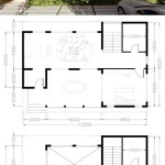
Walls are the primary structural elements defining space within a building, and their representation in floor plans is fundamental. In AutoCAD, walls are typically depicted as two parallel lines. The thickness of these lines indicates the type of wall and its construction. For example, thicker lines usually represent load-bearing walls designed to support the weight of the structure, while thinner lines often denote non-load-bearing partitions or interior walls. The type of hatching or fill pattern applied within the wall lines can further specify the wall's material, such as concrete, brick, or wood framing. A solid fill often represents a solid concrete or masonry wall, while a hatched pattern might represent a stud wall with insulation. The key to accurate interpretation lies in correlating the symbols with the drawing's legend or notes, which should explicitly state the conventions used for wall representation.
Furthermore, wall symbols can incorporate annotations indicating specific characteristics. Dimensions of the wall's thickness or length are typically included. Notes might specify the wall's fire rating, soundproofing properties, or the presence of insulation. In some cases, embedded objects within the wall, such as electrical conduits or plumbing pipes, may be represented with their own symbols, often shown as dashed or hidden lines within the wall outline. Careful attention to these details ensures a complete understanding of the wall's construction and function.
Wall junctions, where walls meet or intersect, are also crucial points of information within a floor plan. The drawing should clearly indicate how these junctions are formed. For instance, a simple T-junction between two walls might be depicted with the wall lines simply meeting. However, more complex junctions, such as those involving multiple walls or corners, might require specific detailing to ensure accurate construction. These details might include the use of thickened lines, rounded corners, or specific symbols to indicate the type of connection. Discrepancies in these details could lead to errors during construction, highlighting the importance of precise symbol interpretation.
Interpreting Door and Window Symbols
Doors and windows are essential features that provide access, ventilation, and natural light within a building. Their symbols in AutoCAD floor plans convey information about their type, size, and operation. A door is typically represented by a curved line that indicates the direction of the door swing and a straight line that represents the door itself when closed. The arc's direction indicates whether the door swings inwards or outwards. The length of the straight line represents the width of the door opening. The type of door (e.g., single-leaf, double-leaf, sliding) is indicated by the symbol's configuration. A double-leaf door, for instance, would be represented by two curved lines and two straight lines.
Window symbols generally consist of one or more parallel lines representing the window frame and glazing. The number of lines can indicate the type of window, such as single-hung, double-hung, or fixed. Dashed lines might represent the operable portions of the window, such as sliding sashes. The size of the window is indicated by its dimensions, which are typically annotated on the drawing. Special window types, such as bay windows or skylights, may have unique symbols that clearly differentiate them from standard window representations. Understanding the nuances of these symbols is key to accurately visualizing the fenestration of the building.
In addition to the basic representation, details such as the head height of doors and windows are often included in the annotations. This information is critical for ensuring proper clearances and accessibility within the building. Furthermore, specific door and window schedules are often included as separate tables or drawings, providing detailed specifications for each door and window type, including materials, hardware, and fire ratings. These schedules are integral to the interpretation of door and window symbols and should be consulted in conjunction with the floor plan itself.
Deciphering Plumbing and Electrical Symbols
Plumbing and electrical systems are integral to the functionality of a building, and their representation in floor plans is crucial for coordinating their installation. Plumbing symbols commonly depict fixtures such as toilets, sinks, showers, and bathtubs, as well as pipes and drains. These symbols are often standardized across the industry, but variations may exist. A toilet is typically represented by an oval or circular shape, while a sink is often shown as a rectangular or oval shape with a smaller circle representing the drain. Pipes are represented by lines, often with different line types or colors to indicate the type of pipe (e.g., water supply, drain, vent). Valves and fittings are represented by specific symbols that indicate their function and location within the plumbing system.
Electrical symbols represent outlets, switches, light fixtures, and other electrical components. Outlets are typically represented by circles or squares with specific markings to indicate their type (e.g., standard outlet, GFCI outlet, dedicated outlet). Switches are shown as circles or squares with lines indicating their connection to light fixtures. Light fixtures are represented by a variety of symbols, depending on their type (e.g., recessed light, surface-mounted light, chandelier). Wiring is represented by lines, often with different line types or colors to indicate the voltage and circuit. Electrical panels and distribution boards are represented by rectangular symbols with annotations indicating their capacity and function.
The accurate interpretation of plumbing and electrical symbols requires a thorough understanding of building codes and industry standards. The location and spacing of outlets, for example, are governed by code requirements that ensure safety and accessibility. Similarly, the sizing and routing of pipes and wires must comply with code regulations to ensure proper functioning and prevent hazards. Floor plans typically include legends that define the symbols used for plumbing and electrical components, providing a key reference for interpreting the drawings. Furthermore, separate plumbing and electrical drawings are often created to provide more detailed information about these systems, including riser diagrams and wiring schematics.
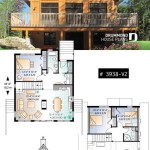
Beyond the basic symbols, floor plans often include symbols for other building elements such as furniture, appliances, stairs, and elevators. The specific symbols used for these elements can vary depending on the designer and the software used to create the drawings. However, the principle remains the same: each symbol must be clearly defined and consistently applied throughout the drawing to ensure accurate communication. In addition, symbols pertaining to HVAC (Heating, Ventilation, and Air Conditioning) systems, fire protection systems (sprinklers, alarms), and security systems are frequently integrated into floor plans, each requiring its own set of standardized or project-specific symbols.
Effective communication in architectural drawings relies heavily on both accurate symbol usage and the inclusion of comprehensive legends. Legends serve as a Rosetta Stone, enabling users to translate the visual language of the floor plan into a concrete understanding of the building's design and function. Without a clear and complete legend, the interpretation of symbols becomes ambiguous, leading to potential errors in construction and miscommunication among stakeholders. Therefore, the creation and maintenance of accurate and accessible legends are paramount to the success of any architectural project using AutoCAD or other CAD software.
In summary, recognizing and understanding the symbols used in AutoCAD floor plan drawings is crucial for anyone involved in the construction or renovation of a building. These symbols provide a standardized and efficient way to communicate complex information about the building's layout, features, and systems. By carefully studying the symbols and the accompanying legends and annotations, professionals can ensure that the building is constructed accurately and efficiently, according to the design intent.

Architectural Graphics 101 Symbols Life Of An Architect

Architectural Symbols In Drawing

Architectural Graphics 101 Symbols Life Of An Architect

Autocad Tutorial Understanding Blocks And Symbols

Interpretation Of Symbols Used In Drawing Autodesk Community

21 Essential Architectural Symbols Everyone Should Know About

Architectural Graphics 101 Symbols Life Of An Architect

Blueprint The Meaning Of Symbols

Floor Plan Symbols Abbreviations Your A Z Guide Cedreo

How To Plan Floor Symbols Architecture