How to Make Floor Plans Using AutoCAD
AutoCAD, a leading computer-aided design (CAD) software, offers a comprehensive suite of tools for creating precise and detailed floor plans. This article provides a step-by-step guide on how to effectively use AutoCAD to develop accurate and professional-looking floor plans.
Before commencing the drawing process, it is crucial to establish a clear understanding of the project requirements. This includes determining the scale of the floor plan, the desired level of detail, and any specific building codes or standards that need to be adhered to. Accurate measurements are also essential for creating a realistic and functional floor plan. It is recommended to gather all necessary dimensions and measurements of the space being planned.
Setting Up the AutoCAD Environment for Floor Plans
The initial step in creating a floor plan with AutoCAD involves configuring the software environment to optimize the drawing process. This includes setting the appropriate units, establishing layers for different elements, and configuring the grid and snap settings.
First, open AutoCAD and create a new drawing. It is advisable to select a template that aligns with the required units of measurement. To change the units, type "UNITS" in the command line and press Enter. A Drawing Units dialog box will appear. Select the desired units (e.g., architectural, decimal, engineering) and the precision level. Architectural units use feet and inches, which are commonly used for floor plans. Confirm the settings by clicking "OK."
Layers are fundamental to organizing and managing different aspects of the floor plan. Layers allow specific elements, such as walls, doors, windows, and furniture, to be grouped together, making it easier to edit and control their visibility. To create layers, type "LAYER" in the command line and press Enter. The Layer Properties Manager will appear. Click the "New Layer" icon to create a new layer. Give each layer a descriptive name (e.g., "Walls," "Doors," "Windows," "Furniture"). Assign different colors and linetypes to each layer to visually distinguish between them. For example, walls can be assigned a solid line and a dark color, while furniture can be assigned a different color and a lighter line weight. Ensure to establish distinct line weights for each layer to differentiate prominent features like walls from less important details.
The grid and snap settings aid in creating accurate and precise drawings. The grid provides a visual reference, while the snap settings allow the cursor to automatically snap to specific points, such as grid intersections or endpoints of lines. To configure the grid and snap settings, type "DSETTINGS" in the command line and press Enter. The Drafting Settings dialog box will appear. In the "Snap and Grid" tab, enable the "Snap On" and "Grid On" options. Set the snap spacing and grid spacing according to the desired level of precision. For example, a snap spacing of 1 inch and a grid spacing of 1 foot can be suitable for architectural floor plans. In the "Object Snap" tab, select the desired object snap options, such as "Endpoint," "Midpoint," "Intersection," and "Center." These options will allow the cursor to snap to the endpoints, midpoints, intersections, and centers of objects, making it easier to draw accurate lines and shapes.
Drawing Walls, Doors, and Windows
With the AutoCAD environment properly configured, one can begin drawing the structural elements of the floor plan, namely walls, doors, and windows. Accuracy and attention to detail are important during this phase.
Walls form the foundation of any floor plan. Begin by drawing the exterior walls of the building. Select the "Line" tool from the Draw panel or type "L" in the command line and press Enter. Specify the starting point of the first wall and then enter the length and angle of the wall. Alternatively, one can use the Ortho mode (press F8) to constrain the lines to horizontal and vertical directions. Repeat this process to draw all the exterior walls. Once the exterior walls are drawn, draw the interior walls in a similar manner. Ensure that the walls are properly connected and aligned. The "Trim" command (type "TR" and press Enter) can be used to clean up intersecting lines and create clean wall junctions. Input the correct wall thickness by using the offset command. This can be achieved by typing "OFFSET" in the command line, pressing enter, specifying the desired thickness, and then selecting the existing wall lines to create parallel lines representing the inner and outer surfaces of the walls. Place each wall set on the "Walls" layer defined earlier.
Doors and windows provide access and natural light to the space. To insert doors and windows, first create openings in the walls where they will be placed. Use the "Trim" command to remove the wall segments where the doors and windows will be located. Next, draw the door and window symbols. These symbols can be created using lines, arcs, and other drawing tools. A simpler alternative is to use pre-drawn door and window blocks. Blocks are reusable objects that can be inserted into the drawing multiple times. AutoCAD comes with a library of pre-defined blocks, or one can create custom blocks. To insert a block, type "INSERT" in the command line and press Enter. The Insert dialog box will appear. Select the desired block from the library or browse to a custom block file. Specify the insertion point, scale, and rotation angle of the block. Place each door and window on the corresponding "Doors" and "Windows" layers. Ensure that the doors are drawn with the correct swing direction.
When drawing doors and windows, consistent use of a standard symbol library is recommended. This helps maintain uniformity in the drawing and makes it easier for others to understand the floor plan. The placement of doors and windows should also consider factors such as natural light, ventilation, and circulation paths. Ensure that doors do not obstruct walkways or furniture placement.
Adding Dimensions, Annotations, and Furniture
Once the structural elements of the floor plan are in place, add dimensions, annotations, and furniture to complete the drawing. These elements provide essential information about the size and layout of the space.
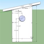
Dimensions indicate the length and width of various elements in the floor plan. Use the "Dimension" tool from the Annotate panel to add dimensions to the walls, doors, windows, and other features. There are different types of dimensions, such as linear, aligned, angular, and radial. Select the appropriate type of dimension based on the element being measured. For linear dimensions, specify the starting and ending points of the dimension line, and then position the dimension text. Adjust the dimension settings, such as the text size, arrow size, and offset distance, to ensure that the dimensions are clear and legible. Place the dimensions on a separate "Dimensions" layer.
Annotations provide additional information about the floor plan, such as room names, material specifications, and notes. Use the "Text" tool from the Annotate panel to add annotations to the drawing. Specify the starting point of the text, the text height, and the rotation angle. Type the desired text and then click outside the text box to finish. Adjust the text style, such as the font, size, and color, to ensure that the annotations are readable. Place the annotations on a separate "Annotations" layer.
Furniture adds context and realism to the floor plan. Insert furniture blocks from the AutoCAD library or create custom furniture blocks. The approach mirrors the process for inserting door and window blocks. Ensure that the furniture is drawn to scale and that it is placed in a realistic arrangement. Consider factors such as traffic flow and functionality when arranging the furniture. Place the furniture on a separate "Furniture" layer. It is beneficial to source or create a library of commonly used furniture blocks to streamline the process and maintain consistency across multiple projects. This library may include items such as chairs, tables, beds, and appliances.
By carefully configuring the AutoCAD environment, accurately drawing the structural elements, and adding dimensions, annotations, and furniture, one can create detailed and professional floor plans that meet the specific needs of a project.

Making A Simple Floor Plan In Autocad Part 1 Of 3

How To Draw Floor Plans In Autocad Edrawmax

How To Draw Floor Plans In Autocad Edrawmax

Autocad Drawing And Coohom Design 3d Fast Rendering Blog

Autocad Simple Floor Plan For Beginners 1 Of 5

How To Make House Floor Plan In Autocad Fantasticeng

How To Draw Autocad Floor Plan Cad Cam Blog

Is Autocad The Best Floor Plan For Estate Agents Elements Property

Floor Plan Create 2d 3d Plans Autodesk

First Floor Plan Of Residence Detail Presented In This Autocad Drawing File 2d Auto Cad Ca Layout