Architectural Plan of a House: A Comprehensive Guide
An architectural plan of a house serves as the foundational blueprint for the entire construction process. It's a detailed set of drawings that communicate the design intent to builders, contractors, and other stakeholders involved in bringing the homeowner's vision to life. Understanding the components and nuances of an architectural plan is crucial for anyone involved in building or renovating a house. This document encompasses a wide range of information, from the precise dimensions of rooms to the placement of electrical outlets and plumbing fixtures. The accuracy and clarity of these plans are paramount to ensuring a successful and efficient construction project.
The process of creating an architectural plan typically begins with a thorough consultation between the architect and the homeowner. This initial phase is dedicated to understanding the homeowner's needs, preferences, and budget. The architect will gather information about the desired size of the house, the number of rooms, the architectural style, and any specific features that the homeowner wants to incorporate. This information is then used to develop preliminary sketches and conceptual designs, which are presented to the homeowner for feedback. The design is refined iteratively based on this feedback, eventually leading to a finalized architectural plan.
A well-executed architectural plan not only guides the construction process but also helps to prevent costly errors and delays. By providing a clear and detailed roadmap for the project, it minimizes the chances of miscommunication and ensures that all parties are working towards the same goal. Furthermore, the plan serves as a crucial document for obtaining building permits and complying with local zoning regulations. It is a legal requirement in most jurisdictions to have approved architectural plans before commencing any construction work.
Key Components of an Architectural Plan
An architectural plan is not a single drawing but a collection of various drawings, each representing different aspects of the house. These drawings work together to provide a comprehensive overview of the design. Key components include the site plan, floor plans, elevations, sections, and detailed drawings.
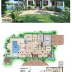
The Site Plan shows the location of the house on the property. It includes information such as property lines, setbacks (the required distance between the house and the property lines), easements, existing structures, landscaping, and utilities. The site plan is crucial for ensuring that the house is properly positioned on the lot and complies with all applicable regulations. It also helps to determine the optimal orientation of the house to maximize sunlight and views.
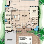
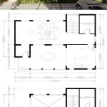
Floor Plans are arguably the most important part of the architectural plan. They are bird's-eye views of each floor of the house, showing the layout of rooms, walls, doors, windows, stairs, and other features. Floor plans include dimensions, annotations, and symbols that provide detailed information about the size and location of each element. They are essential for understanding the flow of space within the house and for planning the placement of furniture and fixtures.
Elevations are exterior views of the house, showing the front, rear, and sides. They depict the appearance of the house from the outside, including the roofline, windows, doors, and exterior finishes. Elevations provide a visual representation of the architectural style and help to coordinate the design of the different facades. They also show the vertical dimensions of the house, such as the height of the roof and the height of the windows.
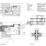
Sections are cut-through views of the house, showing the internal structure and construction details. They reveal the relationship between different floors, the roof structure, and the foundation. Sections provide valuable information about the structural integrity of the house and the methods used to construct it. They also show the location of insulation, plumbing, and electrical wiring.
Detailed Drawings provide enlarged views of specific elements of the house, such as windows, doors, stairs, and built-in cabinets. These drawings show the construction details of these elements, including the materials, dimensions, and connections. Detailed drawings are essential for ensuring that these elements are built according to the architect's specifications.
Understanding Key Symbols and Notations
Architectural plans utilize a standardized set of symbols and notations to convey information efficiently. These symbols represent various building components and systems, and understanding them is crucial for interpreting the plans correctly. Some common symbols and notations include those for walls, doors, windows, electrical outlets, plumbing fixtures, and structural elements.
Wall Symbols typically consist of two parallel lines that represent the thickness of the wall. Different types of walls, such as exterior walls, interior walls, and load-bearing walls, are often indicated by different line weights or fill patterns. Dimensions are usually given to the center of the wall or to the face of the wall, depending on the convention used by the architect. The type of wall construction (e.g., brick, concrete block, wood frame) is usually specified in a separate schedule or note.
Door Symbols usually show the swing direction of the door and the width of the door opening. A curved line indicates the arc of the door swing. The door width is typically indicated by a dimension next to the symbol. The door type (e.g., solid core, hollow core, glass panel) may be specified in a door schedule.
Window Symbols typically show the type of window (e.g., casement, double-hung, sliding) and the size of the window opening. The window height is usually indicated by a dimension above the symbol, and the window width is indicated by a dimension next to the symbol. The window material (e.g., wood, vinyl, aluminum) may be specified in a window schedule.
Electrical Symbols represent electrical outlets, switches, light fixtures, and other electrical components. Each type of component has its own unique symbol. For example, a standard duplex outlet is typically represented by a circle with two lines inside, while a switch is represented by a triangle. The voltage and amperage of the electrical system are usually specified in a separate electrical plan.
Plumbing Symbols indicate the location of plumbing fixtures, such as sinks, toilets, showers, and bathtubs. They also show the location of supply lines and drain lines. Each type of fixture has its own unique symbol. The size and type of pipes are usually specified in a plumbing schedule.
Structural Symbols represent structural elements such as columns, beams, and footings. These symbols are used to indicate the size and location of these elements. The material and load-bearing capacity of the structural elements are usually specified in a structural engineering plan.
The Role of Technology in Architectural Planning
Modern architectural planning relies heavily on computer-aided design (CAD) and building information modeling (BIM) software. These technologies have revolutionized the design process, allowing architects to create more accurate, detailed, and efficient plans. CAD software enables architects to create two-dimensional (2D) drawings electronically, while BIM software allows them to create three-dimensional (3D) models of the house. These models can be used to visualize the design, identify potential conflicts, and generate construction documents.
CAD software has significantly improved the speed and accuracy of drafting. It allows architects to easily create and modify drawings, making it easier to explore different design options. CAD software also allows for the creation of reusable blocks and symbols, which can save time and reduce errors. Furthermore, CAD drawings can be easily shared and distributed electronically, facilitating collaboration between different parties involved in the project.
BIM software takes architectural planning to the next level by creating a virtual representation of the entire building, including all of its components and systems. This model can be used to analyze the building's performance, identify potential problems, and coordinate the work of different trades. BIM software also allows for the generation of accurate cost estimates and schedules, which can help to control project costs and timelines.
The use of BIM software also enhances collaboration among different professionals involved in the project, such as structural engineers, mechanical engineers, and electrical engineers. By sharing a common model, these professionals can identify and resolve potential conflicts early in the design process, reducing the risk of costly changes during construction. BIM software also facilitates the creation of clash detection reports, which automatically identify areas where different building systems are interfering with each other.
Furthermore, BIM models can be used to create realistic renderings and visualizations of the house, allowing homeowners to see what the finished product will look like before construction begins. This can help to ensure that the design meets the homeowner's expectations and to make any necessary changes before it's too late. BIM models can also be used for energy analysis, helping to optimize the building's performance and reduce its environmental impact.
In conclusion, the architectural plan of a house is a complex and comprehensive document that serves as the foundation for the entire construction process. Understanding the key components, symbols, and notations of an architectural plan is essential for anyone involved in building or renovating a house. The use of technology, such as CAD and BIM software, has significantly improved the efficiency and accuracy of architectural planning, allowing architects to create more sustainable and innovative designs.

House Plans How To Design Your Home Plan

House Plans How To Design Your Home Plan

Floor Plan Creator And Designer Free Easy App

House Plans Home Floor Architecturalhouseplans Com

Floor Plan Wikipedia

Plan 4525 Design Studio Architectural House Plans Floor Dream

How To Draw A Floor Plan Live Home 3d

How To Read A Floor Plan With Dimensions Houseplans Blog Com

Floor Plan Wikipedia

Where You Can Buy House Plans Live Home 3d