Essential Aspects of Civil Engineering Drawing House Plans
Civil engineering drawing house plans are vital components of any construction project. They provide a detailed visual representation of the proposed structure, enabling architects, engineers, and contractors to plan and execute the project effectively. Here are some essential aspects to consider when creating or interpreting civil engineering drawing house plans:
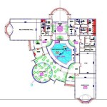
1. Floor Plans
Floor plans are horizontal cross-section drawings that show the layout of each floor in the house. They include the placement of rooms, walls, doors, windows, and other structural elements. Engineers must ensure that floor plans adhere to building codes and regulations, including accessibility and fire safety requirements.
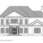
2. Elevations
Elevations are vertical projections that depict the exterior facades of the house from different angles. They provide a clear understanding of the building's height, proportion, and architectural style. Engineers must consider factors such as sunlight exposure and ventilation when designing elevations.
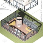
3. Sections
Sections are vertical cross-section drawings that show the interior structure of the house. They reveal the thickness of walls, ceiling heights, and the relationship between different spaces. Sections help engineers determine the load-bearing capacity of the structure.
4. Construction Details
Construction details are specialized drawings that provide specific instructions for constructing critical structural elements. They include details of foundations, framing, roofing, and finishes. Engineers must ensure that these details comply with standard construction practices and material specifications.
5. Scales and Dimensions
Accurate scales and dimensions are crucial for creating precise house plans. The scale indicates the ratio between the drawing and the actual structure, while dimensions specify the size of each element. Precise scales and dimensions enable engineers to calculate material quantities, estimate costs, and avoid construction errors.
6. Symbols and Conventions
Civil engineering drawing house plans use standardized symbols and conventions to represent different structural elements. These symbols ensure clarity and uniformity in the interpretation of drawings. Engineers must be familiar with these symbols to avoid misinterpretations.
7. Coordination with Other Disciplines
Civil engineering drawing house plans must coordinate with drawings from other disciplines, such as electrical, plumbing, and HVAC. This coordination ensures that all elements of the building are compatible and function seamlessly. Engineers must collaborate closely with professionals from other disciplines to prevent clashes or discrepancies.
8. Revisions and Updates
Civil engineering drawing house plans are subject to revisions and updates as the design progresses or changes are made during construction. Engineers must maintain clear documentation of these revisions and communicate them promptly to all stakeholders involved in the project.
Conclusion
Civil engineering drawing house plans are essential tools for planning and constructing any building. They provide a comprehensive visual representation of the structure, enabling engineers to analyze, design, and execute construction effectively. By adhering to industry standards, using accurate scales and dimensions, and coordinating with other disciplines, engineers can create precise and functional house plans that ensure a successful construction project.

Top 50 Amazing House Plan Ideas Engineering Discoveries Simple Plans Model 40x60

House Plans Home Residential

Best 2024 House Design Idea For 30 By Feet Civil Engineering S

Pin On A R C H I T E U

Pin By Shobhit Dixit On Bhai Small House Elevation Design Floor Plans Duplex

Diffe Types Of Building Plans The Constructor

Where You Can Buy House Plans Live Home 3d

Residential Design Red Hook Engineering

What Is Included In A Set Of Working Drawings Best Ing House Plans By Mark Stewart Home Design

Floor Plan Wikipedia