Electrical Panel Floor Plan Symbol Dwg: A Comprehensive Guide
Electrical panel schedules and floor plan symbols are essential components of building design and construction documentation. They provide a visual representation of the electrical distribution system, aiding electricians, contractors, and building managers in understanding the power layout and facilitating effective installation and maintenance.
A critical aspect of these drawings is the accurate and standardized representation of electrical panels. Using a standardized symbol ensures clear communication and minimizes the risk of misinterpretations that could lead to costly errors during construction or future maintenance.
DWG, or Drawing, is a file format native to AutoCAD, a widely used computer-aided design (CAD) software. DWG files contain all the information necessary to reproduce a drawing, including lines, shapes, text, and dimensions. Using DWG files for electrical panel floor plan symbols ensures compatibility across different CAD platforms, enabling seamless collaboration among project stakeholders.
Several factors contribute to the importance of using accurate electrical panel floor plan symbols in DWG format. Primarily, they serve as a visual guide for electricians during the installation process. The symbols pinpoint the exact locations of the panels, allowing for efficient placement and wiring. Accurate representation also helps prevent conflicts with other building systems, such as plumbing and HVAC, during the construction phase.
Beyond installation, these symbols play a crucial role in ongoing maintenance and troubleshooting. They allow facility managers and maintenance personnel to quickly locate panels for inspection, repair, or upgrades. This streamlined access minimizes downtime and improves overall building maintenance efficiency.
Furthermore, accurate DWG symbols are vital for compliance with building codes and regulations. Building inspectors rely on these drawings to verify that the electrical system meets safety standards. Clear and consistent symbols ensure a smooth inspection process and contribute to obtaining necessary permits and approvals.
Several key elements should be included within or alongside an electrical panel symbol in a DWG file. These include the panel's designation or name, which helps distinguish it from other panels in the system. This designation might be a numerical identifier or a descriptive name related to the area it serves.
The panel schedule, typically located on the same drawing or a linked sheet, provides further details about the panel's contents. This schedule lists the circuits connected to the panel, their amperage ratings, and the type of overcurrent protection devices used. The panel symbol itself might also indicate the number of circuits or the main breaker amperage.
Additionally, the symbol should clearly indicate the panel's mounting type, whether it's surface-mounted, flush-mounted, or freestanding. This information is crucial for proper installation and ensures the panel is appropriately secured.
Accessibility considerations should also be reflected in the drawing. Clear space around the panel must be indicated to allow for maintenance and access to the internal components. This clear space is often mandated by building codes and ensures safe operation.
Several resources are available for obtaining accurate electrical panel floor plan symbols in DWG format. Many CAD software packages include libraries of standard electrical symbols, including panel representations. Online libraries and CAD block websites also offer a wide selection of DWG symbols that can be downloaded and incorporated into drawings.
When selecting DWG symbols, it's important to ensure they adhere to relevant industry standards, such as those established by the National Electrical Manufacturers Association (NEMA) and the American National Standards Institute (ANSI). Using standardized symbols promotes clarity and consistency across different projects and jurisdictions.
The use of dynamic blocks in AutoCAD can further enhance the efficiency of working with electrical panel symbols. Dynamic blocks allow for the creation of flexible symbols that can be adjusted to different sizes and configurations without the need to redraw the entire symbol. This feature saves time and reduces the risk of errors.
Proper layering and organization within the DWG file are essential for maintaining a clear and manageable drawing. Placing electrical symbols on a dedicated layer allows for easy visibility control and simplifies the process of generating different views of the drawing. This is particularly important in complex projects with numerous electrical components.
Employing attributes within the DWG symbols enables the linking of non-graphical data to the symbol. This can include information such as the panel's manufacturer, model number, or installation date. This data can be extracted for use in schedules and reports, streamlining documentation and asset management.
Regularly updating and maintaining the DWG library ensures that symbols remain current and compliant with the latest standards. Keeping track of revisions and ensuring that all project stakeholders are using the same version of the library minimizes discrepancies and promotes accuracy.
Effective utilization of electrical panel floor plan symbols in DWG format is crucial for efficient and accurate electrical system design, installation, and maintenance. By adhering to industry standards and employing best practices, construction professionals can leverage these symbols to improve communication, minimize errors, and ensure the safe and reliable operation of electrical systems in buildings.

Cad Electrical Symbols Blocks Drawings Free Cnclathing

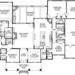
Cad Architect Drawing Electrical Symbols Example Residential

Electrical Symbols Dwg Free Cad Blocks

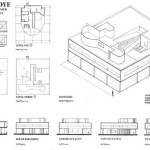
Electrical Plans And Panel Layouts Design Presentation

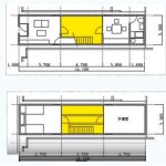
House Electrical Installation Dwg

Symbols Legend Dwg Free Cad Blocks

Electrical Symbols Dwg Block For Autocad Designs Cad

Cad Architect Drawing Electrical Lighting Symbols Example Residential

House Electrical Plans Ensuring Safety And Efficiency
Free Electric And Plumbing Symbols Autocad Blocks Drawings Center