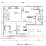
How to Create a Floor Plan Using AutoCAD
AutoCAD is a powerful computer-aided design (CAD) software widely used by architects, engineers, and designers to create precise 2D and 3D drawings. Creating floor plans is a fundamental application of AutoCAD, enabling professionals to visualize and document building layouts accurately. This article provides a comprehensive guide on how to create a floor plan using AutoCAD, covering essential steps and best practices.
Before starting any drawing, proper preparation is paramount. This involves setting up the AutoCAD environment to ensure accuracy and efficiency throughout the design process. Incorrect initial settings can lead to errors and rework later on.
Begin by launching AutoCAD. Upon opening the software, it is crucial to configure the drawing environment. This includes setting the units of measurement, drawing limits, and layers. Utilizing layers effectively is vital for organizing the drawing and controlling the visibility of different elements.
To set the units, type "UNITS" in the command line and press Enter. A Drawing Units dialog box will appear. Select the desired unit of measurement (e.g., architectural, decimal, engineering) from the "Type" dropdown menu. For architectural drawings, "Architectural" is often the most appropriate choice. Further, specify the precision, representing fractions of an inch or decimal places. Click "OK" to save the unit settings.
Next, setting the drawing limits defines the boundaries of the drawing area. Type "LIMITS" in the command line and press Enter. The command line will prompt for specifying the lower-left corner; typically, this is set to 0,0. Press Enter to accept the default. Then, specify the upper-right corner of the drawing area. This depends on the size of the floor plan. For a typical residential plan, a value like 48',36' (48 feet by 36 feet) may be adequate. Press Enter to finalize the drawing limits.
After setting the limits, it is important to zoom to the extent of the drawing area. Type "ZOOM" in the command line and press Enter. Then, type "A" (for All) and press Enter. This ensures that the entire drawing area is visible on the screen.
Layers are crucial for organizing different elements of the floor plan, such as walls, doors, windows, and furniture. Create layers for each of these categories to easily control their visibility, color, and line type. To manage layers, type "LAYER" in the command line and press Enter to open the Layer Properties Manager. In the Layer Properties Manager, click the "New Layer" icon to create a new layer. Assign a descriptive name to each layer (e.g., "Walls," "Doors," "Windows"). Specify the color, line type, and line weight for each layer to visually differentiate the elements. Activate the current layer by selecting it and clicking the green checkmark icon.
Drawing the Walls
With the preparatory work complete, the next step is to draw the walls. This is a fundamental element of the floor plan and must be drawn accurately. Use the "LINE" command to draw the walls, specifying the thickness and length according to the design specifications. It is important to ensure orthogonality, meaning that walls are drawn at right angles, for accurate representation.
Select the "Walls" layer that was previously created. Type "LINE" in the command line and press Enter. Specify the starting point of the wall by clicking on the drawing area or typing coordinates. Enter the length of the wall and specify the direction. Use the "ORTHO" mode (press F8) to ensure that the lines are drawn horizontally or vertically, maintaining right angles. After drawing the first wall, continue drawing subsequent walls by specifying their lengths and directions, creating a closed outline of the building's exterior walls. Use the "CLOSE" command to connect the last wall to the starting point, completing the outline.
To specify the wall thickness, use the "OFFSET" command. Type "OFFSET" in the command line and press Enter. Specify the offset distance, which represents the wall thickness (e.g., 6 inches). Select the wall outline that was previously drawn. Click inside the outline to create an inner line representing the inner edge of the wall. The space between the outer and inner lines represents the wall thickness. Use the "TRIM" command to clean up the corners where the outer and inner lines intersect. Type "TRIM" in the command line and press Enter. Select the lines to be trimmed and press Enter.
For interior walls, repeat the same process as with exterior walls, ensuring that they are properly aligned and meet the design specifications. Use the "LINE" and "OFFSET" commands to draw the interior walls, specifying their lengths and thicknesses accordingly. Ensure that all walls are connected to create a complete and accurate representation of the building's layout.
Adding Doors and Windows
Once the walls are drawn, the next step is to add doors and windows. These elements are essential for indicating access points and natural lighting in the floor plan. Properly sized and positioned doors and windows are crucial for functionality and aesthetics.
Select the "Doors" layer. Use the "LINE" command to draw the opening for the door in the wall. The width of the opening should correspond to the standard door size. Next, draw the door itself using the "LINE" and "ARC" commands. Specify the hinge point and the swing direction of the door. An arc is used to represent the door's swing. The door swing should not obstruct pathways or furniture placement. Add a door symbol to the drawing to clearly indicate the type and direction of the door.
Select the "Windows" layer. Use the "LINE" command to draw the opening for the window in the wall. The width and height of the opening should correspond to the window size. Add a window symbol to represent the window within the opening, typically using lines and a cross. Consider the window type (e.g., casement, sliding) when drawing the symbol. Position the windows strategically to maximize natural light and ventilation.
To ensure consistency, create blocks for standard door and window sizes. A block is a collection of objects that are treated as a single object. To create a block, select the objects that comprise the door or window symbol. Type "BLOCK" in the command line and press Enter. Specify a name for the block (e.g., "Standard Door," "Double Hung Window"). Select a base point for the block (e.g., the hinge point of the door). Click "OK" to create the block. Now, the block can be inserted multiple times in the drawing using the "INSERT" command. This saves time and ensures consistency in the representation of doors and windows.
Adding Annotations and Dimensions
The final step is to add annotations and dimensions to the floor plan. Annotations provide labels for rooms and other features, while dimensions indicate the sizes and distances of various elements. Accurate annotations and dimensions are essential for communicating the design intent to contractors and other stakeholders.
Select the "Text" layer. Use the "TEXT" command to add room names and other labels to the floor plan. Type "TEXT" in the command line and press Enter. Specify the starting point for the text, the text height, and the rotation angle. Type the text and press Enter. Position the text appropriately within the room or feature that it is labeling. Use different text styles for different types of annotations. For example, use a larger font size for room names and a smaller font size for notes.
Select the "Dimensions" layer. Use the "DIMLINEAR" command to add linear dimensions to the floor plan. Type "DIMLINEAR" in the command line and press Enter. Specify the first extension line origin, the second extension line origin, and the dimension line location. AutoCAD will automatically calculate and display the distance between the two points. Ensure that the dimensions are clear, accurate, and easy to read. Use the "DIMSTYLE" command to control the appearance of the dimensions, such as the arrow size, text height, and line weight.
Add overall dimensions to the floor plan, indicating the total length and width of the building. Also, add dimensions for individual rooms, walls, doors, and windows. Use continuous dimensioning to create a chain of dimensions, making it easier to read and understand the overall layout. Avoid overlapping dimensions and annotations to maintain clarity. Update the dimensions as needed if the design changes.
In addition to linear dimensions, use angular dimensions to indicate the angles of non-orthogonal walls or features. Use radial dimensions to indicate the radius of curved walls or features. Use diameter dimensions to indicate the diameter of circular features. Provide sufficient dimensions to fully describe the geometry of the floor plan.
By following these steps, it is possible to create a detailed and accurate floor plan using AutoCAD. Remember to save the drawing regularly and back up the files to prevent data loss. Consistent practice and attention to detail will improve efficiency and accuracy in creating floor plans with AutoCAD.

Making A Simple Floor Plan In Autocad Part 1 Of 3

Basic Floor Plan Drafting In Autocad 7 Steps Instructables

How To Draw Floor Plans In Autocad Edrawmax

Is Autocad The Best Floor Plan For Estate Agents Elements Property

How To Draw Autocad Floor Plan Cad Cam Blog

Autocad Simple Floor Plan For Beginners 1 Of 5

Autocad Drawing And Coohom Design 3d Fast Rendering Blog

How To Draw Floor Plans In Autocad Edrawmax

Autocad Floor Plan Tutorial For Beginners 1

Autocad 2d Bathroom Floor Plans Graphic Design Courses