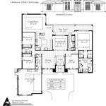
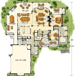
How To Draw Floor Plans In AutoCAD 2010
AutoCAD 2010, despite its age, remains a viable option for creating detailed floor plans. Its robust drafting tools, combined with a relatively straightforward interface, allow users to produce accurate and professional drawings. This article provides a comprehensive guide on utilizing AutoCAD 2010 to develop floor plans, covering essential steps and techniques.
The process begins with setting up AutoCAD 2010 for optimal floor plan creation. This involves configuring units, layers, and other parameters to ensure accuracy and organization throughout the drafting process. Understanding these initial configurations is crucial for avoiding errors and maintaining consistency in the final drawing.
Before initiating the drawing itself, it is essential to gather all necessary information. This includes accurate measurements of the existing space, architectural sketches, and any relevant building codes or regulations. Having this information readily available will streamline the drafting process and minimize potential revisions.
Setting Up AutoCAD 2010 for Floor Plan Creation
The first step is to open AutoCAD 2010 and create a new drawing. After this, the user needs to configure the drawing units. To do this, type "UNITS" into the command line and press Enter. A dialog box will appear. In the "Drawing Units" section, select the desired unit of measurement (architectural, decimal, engineering, fractional, or scientific) from the "Type" dropdown menu. Architectural units are generally preferred for floor plans, as they allow input in feet and inches. Select the desired precision from the "Precision" dropdown menu. In the "Insertion scale" section, choose the appropriate unit of measurement (e.g., inches or millimeters). Click "OK" to save the settings.
Next, establishing appropriate layers is essential for organizing the various elements of the floor plan. Layers allow users to control the visibility and properties of different drawing components, such as walls, doors, windows, and furniture. To create layers, type "LAYER" into the command line and press Enter. The Layer Properties Manager window will appear. Click the "New Layer" button (represented by a yellow sun icon) to create a new layer. Assign a descriptive name to each layer, such as "Walls," "Doors," "Windows," "Furniture," and "Dimensions." Assign a color to each layer for visual distinction. Optionally, assign a line type to each layer. For example, a dashed line type might be used for hidden elements. Repeat these steps to create all necessary layers. Close the Layer Properties Manager window when finished.
Finally, set the drawing limits. Drawing limits define the boundaries of the drawing area. To set the drawing limits, type "LIMITS" into the command line and press Enter. AutoCAD will prompt for the lower left corner. Type "0,0" and press Enter. AutoCAD will then prompt for the upper right corner. Enter the coordinates that encompass the area of the floor plan. For example, if the floor plan is 50 feet by 40 feet, you might enter "50',40'" (assuming architectural units). Press Enter. Type "ZOOM" and press Enter. Then type "A" (for All) and press Enter. This ensures that the entire drawing area is visible.
Drawing Walls and Architectural Elements
With the drawing environment configured, the next step is to begin drawing the walls. Select the "Walls" layer from the Layer Control dropdown menu on the ribbon. Use the "LINE" command (type "L" and press Enter) to draw the exterior walls of the building. Input the coordinates or use the cursor to define the start and end points of each wall segment. Ensure that the walls are drawn to the correct dimensions based on the gathered measurements.
Once the exterior walls are complete, draw the interior walls using the same "LINE" command. Pay close attention to wall thicknesses and ensure they are consistent throughout the plan. Use the "OFFSET" command (type "O" and press Enter) to create parallel lines representing the wall thickness. Enter the desired offset distance (e.g., 4 inches or 6 inches) and select the line to offset. Specify the side on which the offset should occur.
To create openings for doors and windows, use the "TRIM" command (type "TR" and press Enter). Select the cutting edges (i.e., the lines that define the opening) and press Enter. Then, select the lines to be trimmed (i.e., the wall segments that need to be removed to create the opening). Use the "LINE" command to close any gaps created by the trimming process. The "FILLET" command (type "F" and press Enter) can be uses to create rounded corners where walls intersect. The radius should be set to zero to create clean corners.
Next, add doors and windows to the floor plan. Select the appropriate "Doors" or "Windows" layer. Doors are typically represented by an arc that indicates the swing direction. Use the "ARC" command (type "A" and press Enter) to draw the door swing. Specify the start point, center point, and end point of the arc. Draw the door itself as a rectangle using the "RECTANG" command (type "REC" and press Enter). Windows are often represented by two parallel lines within the wall opening. Use the "LINE" command to draw these lines. Pay attention to the size and placement of the doors and windows to accurately reflect the architectural specifications.
Adding Details, Annotations, and Dimensions
After the basic architectural elements are in place, the user needs to add details such as furniture, fixtures, and appliances. Select the appropriate layer (e.g., "Furniture," "Fixtures," "Appliances"). Use the various drawing commands (LINE, CIRCLE, RECTANG, ARC) to represent these elements. Alternatively, users can insert pre-drawn blocks of common furniture and fixtures from AutoCAD's DesignCenter or from external block libraries. To access the DesignCenter, type "ADCENTER" into the command line and press Enter. Navigate to the desired block library and drag and drop the blocks into the drawing.
Annotations are essential for providing information about the floor plan. Use the "TEXT" command (type "TEXT" or "MTEXT" and press Enter) to add labels for rooms, walls, doors, and other elements. "TEXT" creates single-line text, while "MTEXT" creates multi-line text. Specify the start point, height, and rotation angle for the text. Use a clear and concise font that is easy to read. Ensure that the text is placed appropriately and does not obscure any important details.
Dimensions are crucial for conveying the exact measurements of the floor plan. Select the "Dimensions" layer. Use the various dimensioning commands (e.g., "LINEAR," "ALIGNED," "ANGULAR") to add dimensions to the walls, openings, and other elements. The "LINEAR" command creates horizontal or vertical dimensions. The "ALIGNED" command creates dimensions parallel to a selected line. The "ANGULAR" command creates angular dimensions. Adjust the dimension settings (e.g., text height, arrow size, units) to ensure they are legible and consistent with the overall drawing style. Use the "DIMSTYLE" command (type "DIMSTYLE" and press Enter) to modify dimension styles.
The addition of hatching and patterns can enhance the visual clarity and convey specific information about materials and finishes. Use the "HATCH" command (type "H" and press Enter) to apply hatch patterns to walls, floors, and other areas. Select the desired hatch pattern from the hatch pattern library. Specify the scale and angle of the hatch pattern. Hatch patterns can be used to represent different types of materials, such as brick, concrete, or wood.
Finally, verify and refine the floor plan. Review the drawing carefully to ensure accuracy and completeness. Check for any errors or omissions. Make any necessary revisions. Use the "AUDIT" command (type "AUDIT" and press Enter) to check the drawing for errors and correct them automatically. Use the "PURGE" command (type "PURGE" and press Enter) to remove unused layers, blocks, and other objects from the drawing, which can reduce the file size and improve performance.
By following these steps, users can effectively create detailed and accurate floor plans in AutoCAD 2010. While newer versions of AutoCAD offer advanced features, AutoCAD 2010 remains a functional tool for producing professional-quality architectural drawings.

Autocad 2010 Tutorial Series Drawing A Floor Plan By Tod Stephens Ebook Barnes Noble

Autocad Tutorials Introduction To Plotting Scale With Layouts In 2010

Autocad Floor Plan Tutorial For Beginners 1

Autocad Floor Plan Tutorial For Beginners 1

Making A Simple Floor Plan In Autocad Part 1 Of 3

Autocad Tutorials Introduction To Drawing A Floorplan In 2010

Exercise Stretch Objects Learning Autocad 2010 And Lt Book

Here We Are Writing About Autocad Tutorial 2010 What Is Auto Cad Learn Dra

Autocad 2d Basics Tutorial To Draw A Simple Floor Plan Fast And Efective Part 1

Create Floor Plans With Autocad Lt Acad Systems Autodesk Gold Partner Training Certification Center


