How To Draw Floor Plans In AutoCAD 2017
Creating accurate and detailed floor plans is a fundamental skill in architectural design. AutoCAD 2017 offers a robust set of tools for this purpose, allowing users to draft, modify, and annotate floor plans efficiently. This article provides a step-by-step guide on how to create floor plans using AutoCAD 2017.
Setting Up the Drawing Environment
Before starting the drawing process, it's essential to configure the drawing environment for optimal performance and accuracy. This includes setting units, drawing limits, and layers.
- Units: Select architectural units (feet and inches) or decimal units (meters or millimeters) based on project requirements. Access the units settings through the UNITS command or the Drawing Utilities dialog box.
- Limits: Define the drawing boundaries using the LIMITS command. This helps control the drawing area and scale.
- Layers: Create layers to organize different elements of the floor plan, such as walls, doors, windows, and furniture. Layers allow for selective visibility and control during the drawing and editing process.
Drawing Walls
Walls form the basic structure of any floor plan. AutoCAD provides several methods for drawing walls.
- Line Command: Use the LINE command to draw individual wall segments. Connect lines to create the desired wall layout.
- Polyline Command: The POLYLINE command allows for drawing continuous wall segments with varying widths and angles.
- Rectangle Command: For rectangular rooms, the RECTANG command provides a quick way to draw the perimeter walls.
- Offset Command: Use the OFFSET command to create parallel walls with a specified offset distance. This is useful for creating interior walls.
Adding Doors and Windows
After drawing the walls, the next step is to add doors and windows. AutoCAD offers pre-defined blocks and dynamic blocks for these elements.
- Insert Block: Use the INSERT command to insert pre-drawn door and window blocks into the wall. These blocks can be customized to specific dimensions and styles.
- Dynamic Blocks: Utilize dynamic blocks for more flexibility. Dynamic blocks allow for adjusting parameters such as width, height, and swing direction within the drawing.
- Create Your Own Blocks: If specific door or window styles are not available, users can create their own blocks using the BLOCK command.
Inserting Furniture and Fixtures
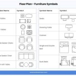
Furnishing the floor plan with furniture and fixtures enhances its visual representation and provides a clearer understanding of the space.
- Furniture Blocks: Access a library of pre-drawn furniture blocks within AutoCAD or download additional blocks from online resources.
- Scale and Rotate: Adjust the scale and rotation of furniture blocks to fit them appropriately within the room spaces.
- Custom Furniture: Create custom furniture shapes using drawing commands like LINE, POLYLINE, ARC, and CIRCLE.
Adding Dimensions and Annotations
Dimensions and annotations are crucial for conveying accurate measurements and information on the floor plan.
- Dimensioning Tools: Use the dimensioning tools (DIMLINEAR, DIMALIGNED, DIMANGULAR, etc.) to add dimensions to walls, doors, windows, and other elements.
- Dimension Styles: Control the appearance of dimensions, such as text height, arrowheads, and units, through the Dimension Style Manager.
- Text Annotations: Add text annotations using the TEXT command to label rooms, indicate materials, or provide other relevant information.
- Multileaders: Use multileaders to connect annotations to specific elements on the floor plan with leader lines.
Using Hatches and Gradients
Hatches and gradients help differentiate different areas within the floor plan and represent materials.
- Hatch Command: Use the HATCH command to fill enclosed areas with predefined patterns or solid fills. This can be used to represent flooring materials, carpets, or tiles.
- Gradient Fill: Create gradient fills for a more visually appealing representation of surfaces or to indicate changes in elevation.
- Hatch Pattern Libraries: Explore the extensive library of hatch patterns available in AutoCAD or create custom hatch patterns.
Creating Layouts and Printing
Once the floor plan is complete, create layouts to prepare for printing or plotting.
- Layout Tabs: Use layout tabs to create different views and scales of the floor plan. This allows for presenting different aspects of the design on separate sheets.
- Viewports: Create viewports within the layout to display specific portions of the model space at different scales. Control viewport scale and visibility for detailed views.
- Page Setup: Configure page size, orientation, and printing settings within the Page Setup Manager.
- Plot: Use the PLOT command or the Print dialog box to print or plot the floor plan to a physical or electronic format.

Basic Floor Plan Drafting In Autocad 7 Steps Instructables

How To Draw Floor Plans In Autocad Edrawmax

Autocad 2024 Tutorial Making A Simple Floor Plan In 2d Drawing

Making A Simple Floor Plan In Autocad Part 1 Of 3

How To Draw Floor Plans In Autocad Edrawmax

Autocad 2024 Basic 2d Floor Plan For Beginner Complete

Draw Floor Plan And Elevation Using Basic Autocad Commands Acad Systems Autodesk Gold Partner Training Certification Center

How To Draw Autocad Floor Plan Cad Cam Blog

Autocad Lt 2024 Help View Autodesk

Autocad 2024 Help File Tab Menu Autodesk


