How to Draw House Floor Plans in AutoCAD
AutoCAD, a computer-aided design (CAD) software application, is widely used by architects, engineers, and designers to create precise 2D and 3D drawings. Drawing house floor plans accurately in AutoCAD requires understanding fundamental commands, drafting techniques, and architectural conventions. This article outlines a comprehensive process for creating professional-quality floor plans using AutoCAD.
Before initiating the drawing process, it is crucial to ensure the AutoCAD environment is properly configured. This involves setting the units of measurement, defining the drawing limits, and establishing appropriate layers. Setting up a template file can streamline this process and ensure consistency across multiple projects.
The initial step is to determine the desired units. For architectural drawings, units are typically set to architectural units (feet and inches) or decimal units (meters or millimeters). This is accomplished through the UNITS command. Accurate input of dimensions is paramount, and the chosen units should reflect the precision required for the project.
Next, the drawing limits need to be defined. This determines the visible area within the AutoCAD workspace. While not strictly defining the boundaries of the drawing, it helps in visualizing the extent of the project. The LIMITS command is used for this purpose, specifying the lower-left and upper-right corners of the drawing area. For a typical house floor plan, a limit range encompassing the entire building footprint is generally appropriate.
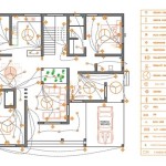
Layers are fundamental for organizing and managing different elements of the floor plan. Layers allow for isolating and controlling the visibility, color, linetype, and lineweight of specific objects. Typical layers for a house floor plan include walls, doors, windows, fixtures, furniture, and annotations. Each layer must be appropriately named and assigned specific properties to enhance clarity and ease of editing.
Creating a template file containing the preconfigured units, limits, and layers saves considerable time and effort in subsequent projects. The template is saved as a .dwt file and can be opened as a starting point for new drawings. This standardization helps ensure consistency in drawing style and organization across all projects.
Establishing the Building Envelope: Walls
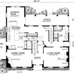
The foundation of any floor plan is the external walls that define the building's outline. Constructing these walls accurately is critical for the overall precision of the plan. The process involves using the LINE, OFFSET, and TRIM commands to create the wall lines and their thickness.
The LINE command is the primary tool for drawing straight line segments. Precise coordinates or direct distance entry can be used to define the length and direction of each line segment. Utilizing object snaps, such as endpoint, midpoint, and intersection, ensures that lines connect accurately and seamlessly. For example, when drawing a rectangular building footprint, the LINE command is used to draw each side of the rectangle, ensuring that the lines are perfectly perpendicular and that the corners meet precisely.
Once the external wall lines are drawn, the OFFSET command is used to create the wall thickness. The OFFSET command creates a parallel copy of a selected object at a specified distance. For a typical wall thickness of 6 inches, the OFFSET command is used to create a parallel line 6 inches inwards from the initial external wall line. This creates the basic representation of the wall's thickness on the floor plan.
The TRIM command is essential for cleaning up the intersections and corners of the wall lines. After offsetting the wall lines, the corners will typically overlap. The TRIM command allows for removing portions of lines that extend beyond the desired boundaries. By selecting the intersecting lines as cutting edges, the TRIM command can quickly and efficiently remove the excess line segments, resulting in clean and precise wall corners.
Internal walls are constructed using the same principles as external walls. The LINE command is used to draw the wall lines, the OFFSET command is used to create the wall thickness, and the TRIM command is used to clean up the intersections. Accurate placement of internal walls is crucial for defining room layouts and ensuring proper spatial relationships within the house.
Incorporating Architectural Elements: Doors and Windows
Doors and windows are essential architectural elements that must be accurately represented on the floor plan. They define access points and allow for natural light and ventilation. AutoCAD provides various tools and techniques for incorporating these elements, including using predefined blocks and creating custom door and window symbols.
Predefined blocks for doors and windows are often available in AutoCAD's library or can be downloaded from online resources. These blocks represent standard door and window types and typically include the swing direction and dimensions. Using predefined blocks saves time and ensures consistency across multiple projects. The INSERT command is used to place these blocks into the drawing at the correct location and orientation.
If predefined blocks are not available or if custom door and window designs are required, creating custom symbols is necessary. This involves drawing the door or window using basic AutoCAD commands such as LINE, ARC, and CIRCLE. The symbol should accurately represent the door or window's dimensions, swing direction, and frame details. Once the symbol is created, it can be saved as a block and reused throughout the drawing.
The placement of doors and windows is critical for functionality and aesthetics. Doors should be placed in convenient locations that allow for easy access to rooms and avoid obstructing furniture placement. Windows should be positioned to maximize natural light and ventilation while considering privacy and energy efficiency. Accurate placement of doors and windows requires careful consideration of the overall layout and design of the house.
The ARC command is particularly useful for representing the swing of doors. A small arc is drawn from the hinge point to the door's open position, indicating the direction of the door's swing. This detail is essential for understanding the door's functionality and avoiding potential collisions with furniture or other objects.
Adding Details and Annotations: Fixtures, Furniture, and Dimensions
The final stage of creating a house floor plan involves adding details such as fixtures, furniture, and dimensions. These elements provide context and clarity to the drawing, allowing for a comprehensive understanding of the layout and spatial relationships within the house.
Fixtures such as toilets, sinks, and bathtubs are typically represented using predefined blocks. These blocks are available in AutoCAD's library or can be downloaded from online resources. The INSERT command is used to place these blocks into the drawing at the correct location and orientation. Accurate placement of fixtures is essential for representing the functionality of bathrooms and kitchens.
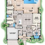
Furniture can be added to the floor plan to illustrate the intended use of each room and to provide a sense of scale. Furniture blocks can be created or downloaded from online resources. The INSERT command is used to place these blocks into the drawing at the correct location and orientation. Consider the dimensions of the furniture and its potential impact on circulation and space utilization.
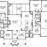
Dimensions are crucial for communicating the precise measurements of the house and its various features. The DIMENSION command is used to create linear, angular, and radial dimensions. Proper dimensioning practices involve placing dimensions in a clear and organized manner, avoiding overlapping dimensions, and using consistent dimension styles. Dimensions should accurately represent the overall dimensions of the house, the room sizes, and the distances between doors, windows, and walls.
Annotations, such as room names and notes, provide additional information and clarity to the floor plan. The TEXT command is used to create text objects. Proper annotation requires using legible fonts, appropriate text sizes, and consistent placement. Annotations should be concise and informative, providing essential details about the function and layout of the house.
Hatching is a technique used to fill areas with patterns or solid colors, providing visual cues and enhancing the clarity of the drawing. The HATCH command is used to create hatch patterns. Typical applications of hatching include representing different floor finishes, such as tile, carpet, or wood flooring. The hatch pattern and scale should be carefully selected to accurately represent the intended material and to avoid overwhelming the drawing.
By following these steps and mastering the fundamental AutoCAD commands, it is possible to create professional-quality house floor plans that accurately represent the design and layout of a building. Consistent practice and attention to detail are essential for achieving optimal results.

Making A Simple Floor Plan In Autocad Part 1 Of 3

How To Draw Floor Plans In Autocad Edrawmax

How To Draw Floor Plans In Autocad Edrawmax

How To Make House Floor Plan In Autocad Fantasticeng

How To Draw Floor Plans In Autocad Edrawmax

Autocad Tutorial Draw A House Floor Plan Free Cad Blocks In Dwg File Format

Autocad Drawing And Coohom Design 3d Fast Rendering Blog

Is Autocad The Best Floor Plan For Estate Agents Elements Property

Draw Your Architectural 2d Floor House Plan In Autocad By Saqibriaz983 Fiverr

Floor Plan Create 2d 3d Plans Autodesk