Creating Isometric Floor Plans in AutoCAD: A Comprehensive Guide
Isometric floor plans offer a unique perspective on a building's layout, showcasing the spatial relationships between different rooms and elements. Creating isometric floor plans in AutoCAD requires a combination of technical skills and an understanding of design principles. This guide will provide you with a step-by-step approach to creating accurate and visually appealing isometric floor plans.
1. Set Up Your Drawing
Begin by opening AutoCAD and creating a new drawing. Set the units to architectural (imperial or metric) and specify the scale of your drawing. It's recommended to work with a scale of 1/4" = 1'-0" or 1:50 for clarity and detail.
2. Draw the Building Outline
Use the LINE command to draw the outline of your building. Start by drawing the rectangle representing the building's footprint. Then, use the OFFSET command to create parallel lines for the walls.
3. Define the Isometric View
To create an isometric view, type "VPOINT" in the command line and specify an isometric view using the "ISO" option. Adjust the camera position and target point to obtain the desired viewing angle.
4. Create Floor Walls
Using the RECTANG command, draw rectangles for each wall section. Position them at the appropriate heights, offsetting them from the floor and ceiling using the OFFSET command.
5. Add Doors and Windows
Use the DOOR and WINDOW commands to insert doors and windows into the walls. Specify the dimensions, location, and swing direction for each door and window.
6. Elevate the Floor
To create the floor, use the REGION command. Select the floor area, excluding the walls, and type "REGION" in the command line. This will create a solid object representing the floor.
7. Add Ceiling and Roof
Repeat the process for the ceiling by drawing a rectangle above the walls and creating a region. For pitched roofs, draw the roof lines and use the LOFT command to connect them to the ceiling.
8. Furnish the Floor Plan
To furnish the floor plan, use the INSERT command to import furniture and other objects from a library or create them using AutoCAD's drawing tools.
9. Add Dimensions and Annotations
Add dimensions and annotations to your floor plan using the DIM and TEXT commands. This will provide additional information about the room sizes and other details.
10. Export the Floor Plan
Finally, export your isometric floor plan in a desired format such as DWG, PDF, or JPEG. This will allow you to share your design with others or use it in other applications.
Creating isometric floor plans in AutoCAD is a valuable skill for architects, designers, and construction professionals. By following these steps and practicing regularly, you can create accurate and visually appealing floor plans that effectively communicate the design intent.

How To Draw A House In Isometric From Autocad 2d Plan

How To Draw Isometric Floor Plan In Autocad Tagalog Paano Gawing Ang

How To Draw A House In Isometric From Autocad 2d Plan

How To Make Isometric Drawings In Autocad Tutorial From 2d Plan Drawing Part 1

Autocad Isometric Drawing Basics

Isometric Drafting In Autocad Tutorial And S

Autocad Isometric Drawing Basics

Isometric Drawings Drafting In Autocad Blog

Isometric Plumbing Layout Basic Tutorial 44

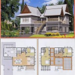
Isometric Elevation View And Floor Plan Details Of Two Story Modern Bungalow Dwg File