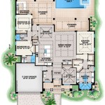
Symbols Floor Plan Definition in AutoCAD Drawing
AutoCAD floor plans represent scaled diagrams of a building’s layout, providing a two-dimensional representation of rooms, walls, doors, windows, and other architectural features. A critical component of an accurate and easily interpretable floor plan is the use of standardized symbols. These symbols function as visual shorthand, allowing architects, engineers, contractors, and other stakeholders to quickly understand the intended design without relying solely on extensive text descriptions. This article delves into the definition of symbols used in AutoCAD floor plans, their importance, and the conventions governing their application.
The consistent and accurate use of symbols in floor plans is essential for clear communication and collaboration during the design, construction, and maintenance phases of a building project. Standardization, often dictated by industry best practices and national or international standards organizations such as the American National Standards Institute (ANSI) or the International Organization for Standardization (ISO), ensures that different professionals can interpret the drawings correctly, reducing the potential for misunderstandings, errors, and costly rework. Furthermore, well-defined symbols facilitate efficient drafting and modification processes within the AutoCAD environment.
Understanding the Purpose of Symbols in Floor Plans
Symbols serve multiple crucial functions in floor plans. Firstly, they provide a compact and efficient way to represent common architectural elements. Instead of drawing a complete depiction of a door every time one appears in the plan, a standardized symbol is used. This saves significant drafting time and reduces file size. Secondly, symbols offer clarity. They clearly differentiate between different types of objects, such as different types of doors, windows, or plumbing fixtures. A single glance at the floor plan should allow someone familiar with the symbols to immediately understand the intended layout.
Thirdly, symbols facilitate consistency. Using standardized and pre-defined symbols ensures that the floor plan adheres to industry standards and is readily understandable by anyone familiar with those standards. This is especially vital in collaborative projects involving multiple professionals or when outsourcing drafting work to different firms. Fourthly, symbols contribute to better organization. By using a consistent set of symbols, the floor plan becomes easier to read and navigate. This is especially important for large and complex buildings with numerous rooms and features.
Finally, symbols promote efficient documentation. They provide a concise and accurate record of the building's design, which can be used for future reference, maintenance, and renovations. A well-documented floor plan with clear symbols is an invaluable asset for building owners and managers.
Common Architectural Symbols in AutoCAD Floor Plans
A wide array of symbols is employed in AutoCAD floor plans to represent different architectural elements. These symbols are often grouped into categories based on the type of element they represent. Below are some common examples:
- Walls: Walls are typically represented by thick, solid lines. The thickness of the line may vary depending on the type of wall (e.g., exterior wall, interior partition). Different hatch patterns or line types might indicate different wall materials (e.g., concrete, brick, wood).
- Doors: A door symbol usually consists of a line representing the door leaf and an arc indicating the swing direction. Different types of doors (e.g., single door, double door, sliding door) are distinguished by variations in the symbol. For instance, a double door might have two door leaves side by side, and a sliding door might be represented by a line with arrows indicating the direction of movement.
- Windows: Window symbols usually involve a thin line representing the window frame and one or more lines indicating the glass panes. The type of window (e.g., casement, awning, sliding) can be represented by variations in the symbol. For example, a casement window might have lines indicating the hinges and the direction of opening.
- Fixtures: Fixtures such as toilets, sinks, bathtubs, and showers are typically represented by simplified shapes that resemble their actual form. These symbols are usually drawn to scale to accurately reflect the size and placement of the fixtures within the room.
- Stairs: Stair symbols consist of a series of parallel lines representing the steps, with an arrow indicating the direction of ascent. The number of steps is usually indicated, and annotations might include information about the riser height and tread depth.
- Furniture: Furniture symbols are used to represent items such as tables, chairs, beds, and sofas. They are usually drawn to scale and placed in the floor plan to indicate the intended layout of the furniture within the rooms.
- Appliances: Appliance symbols represent items such as refrigerators, stoves, dishwashers, and washing machines. Like furniture symbols, they are typically drawn to scale and placed in the floor plan to show the intended location of the appliances.
- Electrical Elements: Electrical symbols include representations of outlets, switches, lights, and other electrical components. These symbols are used to indicate the placement of these elements within the floor plan and are essential for electrical planning and wiring diagrams.
In addition to these common symbols, floor plans may also include symbols for other architectural elements such as columns, beams, fireplaces, and HVAC equipment. The specific symbols used in a floor plan will depend on the project's scope and the designer's preferences, but it is important to use a consistent and standardized set of symbols to ensure clarity and accuracy.
Best Practices for Using Symbols in AutoCAD Floor Plans
While standard symbols exist, their consistent application and proper management within the AutoCAD environment are crucial for producing high-quality floor plans. Several best practices should be followed to ensure the effective use of symbols:
Firstly, it is important to use a symbol library. Create and maintain a comprehensive library of standard symbols. This library should include all the symbols commonly used in floor plans, organized into logical categories. This ensures consistency across different projects and reduces the time spent searching for and creating symbols.
Secondly, employ block attributes. Utilize block attributes to add information to symbols, such as door sizes, window types, or fixture model numbers. This allows for easy extraction of data from the floor plan and streamlines the process of creating schedules and reports.
Thirdly, maintain layer management. Assign each symbol to a specific layer based on its category (e.g., walls, doors, fixtures). This allows for easy control over the visibility and properties of different elements in the floor plan. For instance, one could easily turn off the "Furniture" layer to view the underlying architectural structure without visual clutter.
Fourthly, ensure scale consistency. Symbols should be drawn to scale and consistently used throughout the floor plan. This ensures that the floor plan accurately represents the dimensions and relationships of the architectural elements. It ensures that the scale of the symbol consistently represents the real-world dimensions of the element it represents.
Fifthly, provide a legend. Include a legend or key that defines all the symbols used in the floor plan. This ensures that anyone who views the floor plan can understand the meaning of the symbols, even if they are not familiar with them. The legend should clearly explain each symbol's meaning and any associated attributes or notations.
Sixthly, regularly update the symbol library. The symbol library should be reviewed and updated regularly to reflect changes in industry standards and best practices. This ensures that the symbols used in floor plans remain current and accurate.
Seventhly, utilize dynamic blocks. Utilize dynamic blocks, where appropriate, to create flexible symbols that can be easily adjusted to different sizes or configurations. This can save time and effort when creating floor plans with varying dimensions or layouts. For example, a dynamic door block could be stretched to fit different door widths without requiring the user to redraw the entire symbol.
Eighthly, implement quality control. Implement a thorough quality control process to ensure that all symbols are used correctly and consistently throughout the floor plan. This includes reviewing the floor plan for errors and inconsistencies, as well as verifying that all symbols are properly annotated and documented.
Ninthly, adopt standard naming conventions. Adopt a standard naming convention for symbols to ensure that they can be easily identified and located within the symbol library. This convention should be logical and consistent, and it should reflect the type of element that the symbol represents.
Following these best practices will significantly improve the clarity, accuracy, and efficiency of creating and using symbols in AutoCAD floor plans. This leads to better communication, reduced errors, and ultimately, successful building projects.
In conclusion, the effective use of symbols in AutoCAD floor plans is paramount for clear communication, accurate representation, and efficient collaboration in architectural projects. By understanding the purpose of symbols, adhering to industry standards, and following best practices for their implementation, architects and designers can create floor plans that are easily understood, accurately reflect the intended design, and contribute to the successful completion of building projects.

Construction Drawing Autocad Symbols
Architectural Symbols In Drawing

Architectural Graphics 101 Symbols Life Of An Architect

Autocad Tutorial Understanding Blocks And Symbols

Architectural Graphics 101 Symbols Life Of An Architect

How To Plan Floor Symbols Architecture

Autocad Symbols Office Management Group

Understanding Architectural Symbols And Their Meanings Archisoup

21 Essential Architectural Symbols Everyone Should Know About

Architectural Symbols For 2d Drawings And Floor Plans How Companies Interpret Them Cad Crowd

