Understanding Symbols in AutoCAD Floor Plans: A Comprehensive Guide
AutoCAD, or Computer-Aided Design, is a sophisticated software widely used in architecture, engineering, and construction (AEC) industries for creating precise 2D and 3D drawings. Floor plans, a fundamental component of architectural documentation, are graphical representations of a building's layout at a specific level. To effectively communicate the design intent, these floor plans rely heavily on symbols that represent various architectural, structural, mechanical, electrical, and plumbing (MEP) elements. Understanding these symbols is crucial for architects, engineers, contractors, and anyone involved in the building process to accurately interpret and execute the design.
This article aims to provide a comprehensive overview of the most common symbols encountered in AutoCAD floor plans, explaining their definitions and meanings. The goal is to equip readers with the knowledge necessary to decipher these drawings, facilitating better communication and reducing the potential for errors during construction or renovation projects.
Architectural Symbols
Architectural symbols represent the physical components that define a building's structure and layout. These symbols are essential for visualizing the spatial arrangement and overall design of a building.
Walls: Walls are typically represented by two parallel lines, the thickness of which corresponds to the actual wall thickness. Different line types, such as dashed lines, may indicate walls above or walls that are to be demolished. Hatch patterns within the wall lines can further differentiate between wall types, such as concrete, brick, or drywall. A specific hatch pattern key or legend should be included in the drawing to avoid ambiguity.
Doors: Doors are symbolized as an arc representing the door swing and a straight line representing the door itself. The direction of the arc indicates the direction in which the door opens. Different door types, such as sliding doors, bi-fold doors, or pocket doors, are represented with distinct symbols to clearly identify their operation. The door swing is critical information for space planning and accessibility considerations.
Windows: Windows are generally depicted as three parallel lines between the wall lines. The center line indicates the glass pane, while the outer lines represent the window frame. Various window types, such as casement windows, awning windows, and sliding windows, can be represented with variations in the symbol, often incorporating elements that suggest the window's operating mechanism. The size and placement of windows are essential for understanding natural light and ventilation strategies.
Stairs: Stairs are represented by a series of parallel lines indicating the individual steps, with an arrow indicating the direction of ascent or descent. The number of steps, the riser height, and the tread depth are often noted adjacent to the stair symbol. Landings are represented by a break in the parallel lines. The placement and design of stairs are crucial for accessibility and building code compliance.
Fixtures: Plumbing fixtures such as toilets, sinks, bathtubs, and showers are represented by stylized symbols resembling their actual shape. These symbols vary slightly depending on the specific fixture type and manufacturer, but the basic representation remains consistent. The placement of fixtures is essential for understanding the layout of bathrooms and kitchens.
Structural Symbols
Structural symbols represent the load-bearing elements that support the building's weight. These symbols are critical for ensuring the structural integrity of the building.
Columns: Columns are typically represented by a solid circle or a square, often with a cross or a filled pattern inside. The size of the symbol corresponds to the column's cross-sectional dimensions. The column grid is usually overlaid on the floor plan to indicate the location of each column. The column grid also assists in aligning other structural and architectural elements.
Beams: Beams are represented by solid lines connecting columns, indicating the supporting structure for the floor above. Different line weights or hatch patterns may indicate different beam sizes or materials. The beam schedule, a separate table within the drawing set, provides further details about the beam specifications, such as the material type, dimensions, and load-bearing capacity.
Bearing Walls: Bearing walls, which support the weight of the roof or upper floors, are represented similarly to regular walls but are often indicated with a specific hatch pattern or a thicker line weight to distinguish them from non-load-bearing walls. The location and type of bearing walls are critical for understanding the building's structural system.
Foundations: Foundation elements, such as footings and foundation walls, are typically shown in dashed lines, indicating that they are below the ground level. The foundation plan, a separate drawing in the set, provides more detailed information about the foundation design, including the dimensions, reinforcement, and soil bearing capacity.
Mechanical, Electrical, and Plumbing (MEP) Symbols
MEP symbols represent the systems that provide essential services to the building, such as heating, ventilation, air conditioning, electrical power, and plumbing. These symbols are crucial for understanding the building's infrastructure.
HVAC (Heating, Ventilation, and Air Conditioning): HVAC symbols represent components such as air ducts, diffusers, thermostats, and air handling units. Air ducts are shown as lines, often with arrows indicating the direction of airflow. Diffusers are represented by small circles or squares, while thermostats are shown as rectangular boxes with a thermometer symbol. The HVAC system design is critical for maintaining a comfortable and healthy indoor environment.
Electrical: Electrical symbols represent components such as outlets, switches, lighting fixtures, and electrical panels. Outlets are typically represented by circles or squares with specific markings to indicate the voltage and amperage. Switches are shown as lines with a toggle symbol, while lighting fixtures are represented by various symbols depending on the fixture type (e.g., recessed lighting, pendant lighting). The electrical plan shows the layout of the electrical system and is essential for safe and efficient power distribution.
Plumbing: Plumbing symbols represent components such as pipes, valves, drains, and plumbing fixtures. Pipes are shown as lines, with different line types or colors indicating different pipe types (e.g., water supply, drain lines). Valves are represented by various symbols depending on the valve type (e.g., gate valve, ball valve). Drains are shown as small circles or squares. The plumbing system design aims to provide potable water and remove wastewater safely and efficiently.
Key Considerations for Interpreting Symbols in AutoCAD Floor Plans
While understanding the basic symbols is essential, it is equally important to consider the following factors when interpreting AutoCAD floor plans:
Drawing Scale: The scale of the drawing indicates the relationship between the dimensions on the drawing and the actual dimensions of the building. The scale is usually indicated in the title block of the drawing. Understanding the scale is crucial for accurately measuring distances and areas on the floor plan.
Line Weights and Types: Different line weights and types (e.g., solid, dashed, dotted) are used to represent different elements and their importance. Thicker lines may indicate walls or structural elements, while dashed lines may indicate hidden elements or elements above. A clear understanding of the line weight and type conventions is essential for accurate interpretation.
Legends and Schedules: Legends and schedules provide detailed information about the symbols used in the drawing, as well as specifications for materials, finishes, and equipment. The legend explains the meaning of each symbol, while the schedules provide information such as door sizes, window types, and fixture specifications. Always refer to the legends and schedules to clarify any uncertainties.
Annotations and Notes: Annotations and notes provide additional information about the design, such as dimensions, material callouts, and specific instructions. These annotations are essential for understanding the design intent and for coordinating the work of different trades.
Revisions: Construction documents often undergo revisions as the design evolves. Always check the revision history to ensure that you are working with the most up-to-date version of the drawing. Revisions are typically indicated in the title block or near the affected area of the drawing.
In summary, a thorough understanding of the symbols used in AutoCAD floor plans is crucial for effective communication and collaboration in the AEC industry. By familiarizing oneself with the various architectural, structural, and MEP symbols, and by considering the drawing scale, line weights, legends, annotations, and revisions, one can accurately interpret these drawings and contribute to the successful completion of building projects.

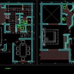
Construction Drawing Autocad Symbols

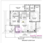
Architectural Symbols In Drawing

Architectural Graphics 101 Symbols Life Of An Architect

Architectural Graphics 101 Symbols Life Of An Architect

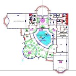
Interpretation Of Symbols Used In Drawing Autodesk Community

Blueprint The Meaning Of Symbols

Autocad Tutorial Understanding Blocks And Symbols

Understanding Architectural Symbols And Their Meanings Archisoup

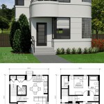
Floor Plan Symbols Meanings Edrawmax

Autocad Symbols Office Management Group