Symbols Floor Plan Definition In AutoCAD Drawings: Meanings List
Floor plans are fundamental drawings used in architecture, engineering, and construction. They provide a top-down view of a building or space, illustrating the arrangement of rooms, walls, doors, windows, and other structural elements. AutoCAD, a widely used computer-aided design (CAD) software, is frequently employed to create these plans. To effectively interpret and utilize AutoCAD floor plans, it's crucial to understand the standardized symbols and conventions used to represent different features. These symbols provide a concise and universally understood visual language, ensuring clear communication between stakeholders involved in the project.
Architectural symbols simplify complex information, conveying detailed specifications without the need for lengthy textual descriptions. These symbols, often based on industry standards and best practices, are designed to be easily recognizable and consistently applied across different drawings. This standardization minimizes ambiguity and reduces the potential for misinterpretations. A comprehensive understanding of these symbols is essential for architects, engineers, contractors, interior designers, and even homeowners who wish to understand their building's layout and features.
The following sections detail common symbols found in AutoCAD floor plans, categorizing them by element type to facilitate easier comprehension. The descriptions aim to provide a practical guide for interpreting these symbols and understanding their implications in the context of building design and construction.
Doors and Windows
Doors and windows are crucial components of any building, providing access, ventilation, and natural light. Their representation in floor plans is standardized to accurately depict their type, swing direction, and dimensions.
Doors: A door is typically represented by a curved line originating from one side of a wall and extending to the doorway opening. This curve indicates the swing direction of the door. A single line across the doorway opening denotes a single-leaf door, while two parallel lines represent a double-leaf door. The direction of the curve indicates whether the door is a left-hand or right-hand swing. The thickness of the line can sometimes represent the thickness of the door itself. Different door types, such as sliding doors or folding doors, are represented with distinct symbols. A sliding door is usually depicted with an arrow indicating the direction of its slide along the wall. A pocket door, which slides into the wall, is generally shown with dashed lines indicating its hidden position when open.
Windows: Windows are generally depicted as a set of parallel lines within the wall, representing the glass panes. The number of lines indicates the number of window panes. Single-hung windows often show a single line with an arrow indicating the movable sash. Double-hung windows are displayed with two parallel lines, each with an arrow indicating the movement of both sashes. Casement windows, which swing outward, are indicated by an arc showing the direction of the swing, similar to a door. Bay windows, which project outward from the wall, are shown with angular lines indicating their outward projection and the panes of glass within. Specific window types might include annotations near the symbol detailing the window material, glazing type, or U-value (a measure of thermal transmittance).
Dimensions are typically provided adjacent to the door and window symbols, specifying their width and height. These dimensions are critical for planning furniture placement, ensuring accessibility, and determining the amount of natural light entering a space.
Walls and Structural Elements
Walls are the primary structural elements of a building, defining its shape and providing support. Their accurate representation in floor plans is essential for understanding the building's layout and load-bearing capabilities.
Walls: Walls are generally represented by thick, solid lines. The thickness of the line often indicates the wall's actual thickness. Different types of walls, such as load-bearing walls, partition walls, and fire-rated walls, can be distinguished by different line types or hatching patterns. Load-bearing walls, which support the weight of the structure above, are usually drawn with thicker lines than non-load-bearing partition walls. Fire-rated walls, designed to resist the spread of fire, are often indicated with a specific hatching pattern or annotation. Dashed lines might represent walls above or elements projected above a certain height, such as a soffit.
Columns: Columns, which provide vertical support, are typically represented by solid squares or circles. Their size indicates their diameter or dimensions. The location of columns is critical for understanding the structural framework of the building. Concrete columns might be represented with a specific hatching pattern to distinguish them from steel columns. Annotations near the column symbol may specify the column material, dimensions, and load-bearing capacity.
Stairs: Stairs are depicted as a series of lines representing the individual steps or treads. An arrow indicates the direction of ascent. The number of steps is usually indicated, and the width of the staircase is also specified. Landings are shown as rectangular areas within the staircase. Escalators are similarly represented, with additional symbols indicating their direction of movement. Elevators are typically shown as a rectangular space with the word "ELEV" inside. They are crucial for accessibility and are always noted with precision.
Dimensions are critical for understanding the wall lengths, column spacing, and staircase dimensions. These measurements are used for calculating material quantities, ensuring structural integrity, and planning the overall layout of the space.
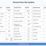
Plumbing and Electrical Fixtures
Plumbing and electrical fixtures are essential for a building's functionality, providing water, drainage, and electrical power. Their representation in floor plans ensures that these systems are properly integrated into the building design.
Plumbing Fixtures: Plumbing fixtures, such as toilets, sinks, and bathtubs, are represented by standardized symbols. A toilet is typically shown as a stylized representation of the bowl and tank. A sink is depicted as a circular or oval shape with faucet symbols. A bathtub is represented by a rectangular shape. Showers are often depicted as a square or rectangular enclosure with a showerhead symbol. Hot water tanks are often shown as a cylindrical symbol with labeled inlet and outlet pipes. The location of these fixtures is important for planning plumbing runs and ensuring proper drainage. The symbols may also include annotations indicating the type of fixture, its dimensions, and any specific requirements.
Electrical Fixtures: Electrical fixtures, such as light fixtures, switches, and outlets, are also represented by standardized symbols. A light fixture is typically shown as a circle with different symbols inside to indicate different lighting types (e.g., recessed lighting, pendant lighting, wall sconces). Switches are represented by a small circle with a line indicating the switch's position. Outlets are shown as circles with different symbols indicating the type of outlet (e.g., standard outlet, GFCI outlet, USB outlet). Smoke detectors are usually depicted as a small circle with a smoke symbol inside. The placement of these fixtures is essential for planning the electrical wiring and ensuring adequate lighting and power distribution throughout the building. Annotations may specify the voltage, amperage, and other electrical characteristics of the fixtures.
HVAC Systems: Heating, ventilation, and air conditioning (HVAC) systems are often represented schematically in floor plans. Symbols for air ducts, registers, and thermostats are used to indicate the location and routing of these systems. These symbols are critical for coordinating the HVAC system with the architectural design and ensuring proper ventilation and temperature control.
Furniture and Equipment
The arrangement of furniture and equipment is a key aspect of interior design and space planning. Their inclusion in floor plans helps visualize the intended use of the space and ensures that it meets the needs of the occupants.
Furniture: Furniture is typically represented by simplified shapes that approximate the actual dimensions and form of the furniture pieces. Sofas are shown as rectangles, chairs as squares or circles, and tables as rectangular or circular shapes. Beds are depicted as rectangular shapes with dimensions corresponding to standard bed sizes. Desks are shown as rectangular surfaces with drawers or cabinets indicated. The arrangement of furniture is crucial for determining traffic flow, ensuring adequate space for movement, and creating a functional and aesthetically pleasing environment.
Equipment: Specialized equipment, such as kitchen appliances, laboratory equipment, or medical equipment, is also represented by standardized symbols or simplified shapes. Refrigerators are shown as rectangular boxes, stoves as squares with burner symbols, and washing machines as rectangular shapes with control panel symbols. The location of equipment is important for planning utility connections, ensuring proper ventilation, and meeting specific functional requirements. Many times equipment manufacturers will provide CAD blocks specifically for their pieces of equipment.
Landscaping: Floor plans can also show basic landscaping elements, with symbols for trees, shrubs, and pathways. Trees are usually depicted as circles or irregular shapes, while shrubs are represented by smaller, rounded shapes. Pathways are shown as dashed lines or hatched areas. Although landscaping details are usually deferred to a landscape plan, major exterior elements are sometimes shown on floor plans.
Annotations and Dimensions
Annotations and dimensions are essential for providing additional information and clarifying the meaning of the symbols in a floor plan. They provide critical measurements and specifications that are used for construction and design.
Annotations: Annotations are text labels that provide additional information about specific elements in the floor plan. They can be used to identify room names, materials, finishes, and other important details. Annotations are typically placed near the element they describe and are connected with leader lines. They should be clear, concise, and easy to read. Standard abbreviations are often used to save space and improve clarity.
Dimensions: Dimensions are lines and numbers that indicate the size and location of various elements in the floor plan. They are crucial for ensuring that the building is constructed according to the design specifications. Dimensions are typically shown in feet and inches (in the United States) or meters and millimeters (in metric countries). They are placed along the walls, doors, windows, and other features, and are aligned to indicate the dimensioned element. Overall dimensions are provided to show the overall size of the building, while interior dimensions indicate the size of individual rooms and spaces. Aligned dimensions ensure the measurement is parallel to the feature, while linear dimensions maintain horizontal or vertical orientation.
Callouts: Callouts are circles or other shapes that enclose a section of the drawing and refer to a separate detail drawing. They are used to provide more detailed information about specific elements that cannot be adequately represented in the overall floor plan. The callout symbol typically includes a number or letter that corresponds to the detail drawing number. Detail drawings provide enlarged views of specific features, showing their construction and materials in greater detail.
Understanding these symbols is foundational for effective communication and collaboration among all parties involved in a construction project. Accuracy and clarity are paramount when interpreting these symbols on the floor plan. Consistent adherence to industry standards ensures that the floor plan serves as a reliable blueprint for the building's construction and future use.

Architectural Graphics 101 Symbols Life Of An Architect

Architectural Symbols In Drawing

Construction Drawing Autocad Symbols

Architectural Graphics 101 Symbols Life Of An Architect

Complete Guide To Floor Plan Symbols Architectural Abbreviations

Understanding Architectural Symbols And Their Meanings Archisoup

Architectural Symbols In Drawing

The Ultimate Guide To Blueprint Symbols

Blueprint The Meaning Of Symbols

Complete Guide To Floor Plan Symbols Architectural Abbreviations